UQQ-5/17-Q12PB-C Murata Power Solutions Inc, UQQ-5/17-Q12PB-C Datasheet - Page 5
UQQ-5/17-Q12PB-C
Manufacturer Part Number
UQQ-5/17-Q12PB-C
Description
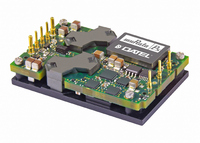
CONV DC/DC 85W 17A 5V T/H
Manufacturer
Murata Power Solutions Inc
Series
UQQr
Type
Isolatedr
Datasheet
1.UQQ-128-Q12PB-C.pdf
(18 pages)
Specifications of UQQ-5/17-Q12PB-C
Output
5V
Number Of Outputs
1
Power (watts)
85W
Mounting Type
Through Hole
Voltage - Input
9 ~ 36V
Package / Case
8-DIP Module, 1/4 Brick
1st Output
5 VDC @ 17A
Size / Dimension
2.22" L x 1.45" W x 0.50" H (56.4mm x 36.8mm x 12.7mm)
Power (watts) - Rated
85W
Operating Temperature
-40°C ~ 85°C
Efficiency
90.5%
Approvals
CSA, cUL, EN, UL
Dc / Dc Converter O/p Type
Fixed
No. Of Outputs
1
Input Voltage
9V To 36V
Power Rating
85W
Output Voltage
5V
Output Current
17A
Approval Bodies
EN, IEC, UL
Supply Voltage
12V
Lead Free Status / RoHS Status
Lead free / RoHS Compliant
3rd Output
-
2nd Output
-
4th Output
-
Lead Free Status / RoHS Status
Lead free / RoHS Compliant, Lead free / RoHS Compliant
Other names
811-1892-5


Specifi cation Notes:
(1) All models are tested and specifi ed with 300 lfm airfl ow, external 1 and 10μF paralleled ceramic/
(2) Input Ripple Current is tested and specifi ed over a 5Hz to 20MHz bandwidth. Input fi ltering is
(3) Note that Maximum Power Derating curves indicate an average current at nominal input voltage.
(4) Mean Time Before Failure is calculated using the Telcordia (Belcore) SR-332 Method 1, Case 3,
(5) The On/Off Control may be driven with external logic or by applying appropriate external voltages
(6) Short circuit shutdown begins when the output voltage degrades approximately 2% from the
(7) The outputs are not intended to sink appreciable reverse current.
Start-up Time
DYNAMIC CHARACTERISTICS
Dynamic Load Response
(50-75-50% load step)
ENVIRONMENTAL
Calculated MTBF (4)
Operating Temperature Range
Operating Temperature Range
Storage Temperature Range
Thermal Protection/Shutdown
Relative humidity
PHYSICAL
Outline dimensions
Baseplate material
Pin material
Pin diameter
Weight
Electromagnetic interference
Safety
Flammability
VIN to VOUT regulated
Remote On/Off
to VOUT regulated
Switching frequency
tantalum output capacitors and a 100μF external input capacitor. All capacitors are low ESR
types. These capacitors are necessary to accommodate our test equipment and may not be
required in your applications. All models are stable and regulate within spec under no-load
conditions.
General conditions for Specifi cations are +25°C, V
noted.
C
At higher temperatures and/or lower airfl ow, the DC/DC converter will tolerate brief full current
outputs if the total RMS current over time does not exceed the Derating curve. All Derating
curves are presented at sea level altitude. Be aware of reduced power dissipation with increas-
ing altitude.
ground fi xed conditions, T
which are referenced to Input Common. The On/Off Control Input should use either an open
collector/open drain transistor or logic gate.
selected setting.
See Derating curves
with baseplate
(no Derating required) (3)(14)
(conducted, external fi lter
required)
IN
= 33μF tantalum, C
BUS
PCBOARD
= 220μF electrolytic, L
= +25°C, full output load, natural air convection.
UQQ-3.3/25-Q12 UQQ-3.3/25-Q48 UQQ-5/17-Q12
50μsec to ±1%
of fi nal value
10msec
5msec
255 ±25kHz
–40 to +105ºC
BUS
IN
= nominal, V
= 12μH.
100μsec to ±1%
of fi nal value
10msec max
5msec max
255 ±25kHz
–40 to +100ºC
OUT
= nominal, full load unless
Certifi ed to UL/cUL 60950-1, CSA-C22.2 No.60950-1, IEC/EN 60950-1, 2nd Edition
www.murata-ps.com
10msec
260 ±25kHz
–40 to +105°C
–40 to +85ºC
with Derating
Designed to meet class B, EN55022, CISPR22
0.04/0.062 inches, 1.016/1.524 mm
+120ºC, measured at thermistor T1
UQQ-5/20-Q48
25msec
225-265kHz
–40 to +105ºC
50μsec to ±1%
(10) Regulation specifi cations describe the deviation as the line input voltage or output load current is
(11) Alternate pin length and/or other output voltages are available under special quantity order.
(12) Overvoltage shutdown on 48V input models can be eliminated under special quantity order. OV
(13) Do not exceed maximum power specifi cations when adjusting the output trim.
(14) Note that the converter may operate up to +105°C with the baseplate installed (+100°C for the
(15) If reverse polarity is accidentally applied to the input, to ensure reverse input protection, always
(16) For On/Off Control on negative-polarity UQQ-3.3/25-Q48N models, the maximum OFF mode
(17) Always connect the sense pins. If they are not connected to a remote load, connect each sense
To +85°C/85% non-condensing
of fi nal value
(8) Output noise may be further reduced by adding an external fi lter. See I/O Filtering and Noise
(9) All models are fully operational and meet published specifi cations, including “cold start” at –40°C.
See mechanical specifi cations
Reduction.
On-board component package temperatures must not exceed +128°C.
varied from a nominal midpoint value to either extreme.
shutdown can be deleted in order to comply with certain telecom reliability requirements. These
requirements attempt continued operation despite signifi cant input overvoltage.
UQQ-3.3/25-Q48). However, thermal self-protection occurs near +120°C Therefore, +105°C is
recommended to avoid thermal shutdown.
connect an external input fuse in series with the +V
input current rating with nominal input voltage.
control voltage is +13.5 Volts. For the ON mode, the range is pin grounded to +1 Volt max.
pin to its respective output at the converter pins.
Wide Input Range Single Output DC/DC Converters
1 ounce (28 grams)
–55 to +125ºC
Copper alloy
Aluminum
UL 94V-0
TBC
UQQ-12/8-Q12
10msec
260 ±25kHz
–40 to +105°C
5msec
UQQ-12/8-Q48
20msec
245 ±20kHz
–40 to +100°C
95μsec to ±1%
–40 to +57ºC
with Derating
of fi nal value
25 Mar 2011 MDC_UQQ.B01 Page 5 of 18
IN
input. Use approximately twice the full
UQQ-15/7-Q12
10msec
260 ±25kHz
–40 to +105°C
50μsec to ±1%
email: sales@murata-ps.com
UQQ Series
of fi nal value
–40 to +85ºC
with Derating
UQQ-24/4-Q12
10msec
260 ±25kHz
–40 to +105°C
50μsec to ±2%
of fi nal value
Related parts for UQQ-5/17-Q12PB-C
Image
Part Number
Description
Manufacturer
Datasheet
Request
R

Part Number:
Description:
DC/DC TH 17A 12-5V Q-brick
Manufacturer:
Murata Power Solutions Inc

Part Number:
Description:
DC/DC TH 17A 12-5V Q-brick
Manufacturer:
Murata Power Solutions Inc

Part Number:
Description:
DC/DC Converter
Manufacturer:
Murata Power Solutions Inc
Datasheet:

Part Number:
Description:
CONV DC/DC 100W 20A 5V T/H
Manufacturer:
Murata Power Solutions Inc
Datasheet:

Part Number:
Description:
CONVERTER, DC/DC, WI, 100W, 5V
Manufacturer:
Murata Power Solutions Inc
Datasheet:

Part Number:
Description:
DC/DC Converter
Manufacturer:
Murata Power Solutions Inc
Datasheet:
Part Number:
Description:
DC/DC Converters & Regulators 48Vin 5Vout 20A neg polarity TH
Manufacturer:
Murata Power Solutions Inc
Datasheet:
Part Number:
Description:
CONV DC/DC 82.5W 25A 3.3V T/H
Manufacturer:
Murata Power Solutions Inc
Datasheet:
Part Number:
Description:
CONV DC/DC 96W 8A 12V T/H
Manufacturer:
Murata Power Solutions Inc
Datasheet:

Part Number:
Description:
CONV DC/DC 96W 8A 12V T/H
Manufacturer:
Murata Power Solutions Inc
Datasheet:

Part Number:
Description:
Transformers 5Vin 5Vout 200mA 4000Vdc 1:1.33 turn
Manufacturer:
Murata Power Solutions Inc
Datasheet:
Part Number:
Description:
POWER SUPPLY
Manufacturer:
Murata Power Solutions Inc
Datasheet:

Part Number:
Description:
DPM LED MINI 2VDC 3.5DIG LP RED
Manufacturer:
Murata Power Solutions Inc
Datasheet:

Part Number:
Description:
CONV DC/DC 1W 5VIN 5VOUT SIP SGL
Manufacturer:
Murata Power Solutions Inc
Datasheet:

Part Number:
Description:
CONV DC/DC 1W 5VIN 3.3V SIP SGL
Manufacturer:
Murata Power Solutions Inc
Datasheet: