TOOLSTICKDA Silicon Laboratories Inc, TOOLSTICKDA Datasheet - Page 4
TOOLSTICKDA
Manufacturer Part Number
TOOLSTICKDA
Description
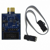
TOOLSTICK DEBUG ADAPTER
Manufacturer
Silicon Laboratories Inc
Series
ToolStickr
Datasheet
1.TOOLSTICKDA.pdf
(6 pages)
Specifications of TOOLSTICKDA
Accessory Type
*
Interface Type
USB
Operating Supply Voltage
2.7 V to 3.6 V
Features
Provides Interface Between PC?S USB Port & Target Device?s In-System Debug/Programming Circuitry
Convert From
USB
Rohs Compliant
Yes
Lead Free Status / RoHS Status
Contains lead / RoHS non-compliant
For Use With/related Products
ToolStick Base adapter
Lead Free Status / Rohs Status
Lead free / RoHS Compliant
For Use With
ToolStick Base Adapter
Lead Free Status / RoHS Status
Lead free / RoHS Compliant, Contains lead / RoHS non-compliant
Other names
336-1347
Available stocks
Company
Part Number
Manufacturer
Quantity
Price
Company:

Part Number:
TOOLSTICKDA
Manufacturer:
Silicon Labs
Quantity:
135


ToolSt ick Debug Adapter
5. Software Setup using a ToolStick Debug Adapter
The Silicon Laboratories Integrated Development Environment (IDE), along with other software tools, are provided
for device development and debugging. The IDE is available for download from the Silicon Laboratories website
and is also available on microcontroller development kit CD-ROMs. Once the IDE has been installed and the hard-
ware has been connected as shown in Section 4, follow the steps below to built a project, connect and download to
a target board using the ToolStick Debug Adapter.
1. Select Project → Open Project... to open a previously
2. Before connecting to the target device, several connection
3. Select USB Debug Adapter in the “Serial Adapter” section.
4. If more than one adapter is connected, choose the
5. Next, the correct “Debug Interface” must be selected. Check
6. Once all the selections are made, click the OK button to
7. Click the Connect button in the toolbar or select Debug →
8. Download the project to the target by clicking the Download
9. Save the project when finished with the debug session to
4
saved project.
options may need to be set. Open the Connection Options
window (shown in Figure 6) by selecting Options →
Connection Options... in the IDE menu.
appropriate serial number from the drop-down list.
the Debug Interface corresponding to the Silicon
Laboratories device on the target board.
close the window.
Connect from the menu to connect to the device.
Code button in the toolbar.
preserve the current target build configuration, editor settings
and the location of all open debug views. To save the project,
select Project → Save Project As... from the menu. Create
a new name for the project and click on Save.
Rev. 0.1
Figure 6. Connection Options
Related parts for TOOLSTICKDA
Image
Part Number
Description
Manufacturer
Datasheet
Request
R

Part Number:
Description:
NiCd - Nickel Cadmium Battery 9.6V 1500MAH
Manufacturer:
FDK Batteries (Formerly Sanyo)
Part Number:
Description:
Battery; Tool; NiCAD; 2.4V; 2400mah
Manufacturer:
Dantona Industries, Inc.
Datasheet:
Part Number:
Description:
Battery, Tool, Dewalt Compatable Replacement Battery, 18v, 1500mAh, Nicad
Manufacturer:
Dantona Industries, Inc.
Datasheet:
Part Number:
Description:
MILWAUKEE CORDLESS DRILL REPLACEMENT BATTERY, 12V, 1.3A
Manufacturer:
MILWAUKEE TOOL

Part Number:
Description:
TOOL-125, 12, 2400, NI-CD, MILWAUKEE:
Manufacturer:
DANTONA INDUSTRIES
Part Number:
Description:
Unspecified Battery types 2.4V 2500mAh EY9021
Manufacturer:
Unspecified
Part Number:
Description:
NiCd - Nickel Cadmium Battery 18V 2400mAh DeWalt Replacement
Manufacturer:
Unspecified
Part Number:
Description:
NiCd - Nickel Cadmium Battery 18V 2200mah
Manufacturer:
Unspecified
Part Number:
Description:
NiCd - Nickel Cadmium Battery 2.4V 1500mAh EY9021
Manufacturer:
Unspecified

Part Number:
Description:
SMD/C�/SINGLE-ENDED OUTPUT SILICON OSCILLATOR
Manufacturer:
Silicon Laboratories Inc
Part Number:
Description:
Manufacturer:
Silicon Laboratories Inc
Datasheet:
Part Number:
Description:
N/A N/A/SI4010 AES KEYFOB DEMO WITH LCD RX
Manufacturer:
Silicon Laboratories Inc
Datasheet:
Part Number:
Description:
N/A N/A/SI4010 SIMPLIFIED KEY FOB DEMO WITH LED RX
Manufacturer:
Silicon Laboratories Inc
Datasheet: