MCP73871DM-VPCC Microchip Technology, MCP73871DM-VPCC Datasheet - Page 12
MCP73871DM-VPCC
Manufacturer Part Number
MCP73871DM-VPCC
Description
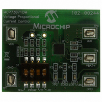
DEMO BOARD FOR MCP73871
Manufacturer
Microchip Technology
Specifications of MCP73871DM-VPCC
Main Purpose
Power Management, Battery Charger
Embedded
No
Utilized Ic / Part
MCP73871
Primary Attributes
1 Cell- Li-Ion / Li-Pol, 4.2V @ 100 ~ 500mA: USB, 1A: AC Adaptor
Secondary Attributes
Safety Timer, Thermal Protection, Automatic Charge Termination and Recharge
Lead Free Status / RoHS Status
Lead free / RoHS Compliant
Lead Free Status / RoHS Status
Lead free / RoHS Compliant, Lead free / RoHS Compliant
Available stocks
Company
Part Number
Manufacturer
Quantity
Price
Company:

Part Number:
MCP73871DM-VPCC
Manufacturer:
Microchip Technology
Quantity:
135


MCP73871 Demo Board with Voltage Proportional Current Control User’s Guide
2.3
DS51812B-page 12
GETTING STARTED
The MCP73871 Demo Board with Voltage Proportional Current Control is fully
assembled and tested for charging a single-cell Li-Ion or Li-Polymer battery with or
without system load.
2.3.1
2.3.1.1
1. Connect the positive battery terminal to V
2. Connect the 5V – 6V DC power supply Negative Terminal to GND (TP1 or TP5).
3. Connect the 5V – 6V DC power supply Positive Terminal to V
4. Connect positive of load to OUT (TP3) on the board and negative of load to GND
5. The maximum current that system load requires should not violate the
6. You should initiate the battery charging cycle when turning CE switch of S1 OFF.
7. The S1 switch #1 in OFF position (SEL - “AC-DC”) allows maximum input current
8. The S1 switch #1 in ON position (SEL - “USB”) limits the input current to meet
9. If switch SEL is in ON position (PROG2), the user has two options for switch #2:
10. If DC power is removed, the load should be supported by the Li-Ion battery.
2.3.2
The resistors that connected at R
current in constant current mode from ac-dc adapter and termination current,
respectively. The relationship between fast charge current and value of R
resistor is illustrated in Figure 2-1. The correspondence of R
Demo Board with Voltage Proportional Current Control is R
which sets the maximum charge current at 1A.
For R
termination current at 100 mA and a 100 kΩ value results a 10 mA termination point.
Read carefully the additional information on the schematic in A.2 “Board – Sche-
matic”. The boards comes with R
- OFF - limits the total input current to 500 mA
- ON - for maximum input current at 100 mA.
Note 1:
terminal to GND (TP1 or TP5).
(TP1 or TP5). The system load can be a power resistor or E-Load.
specification of Li-Ion battery manufacturer (typical at 1C or less) or 1A for safety
and performance concerns.
Turning the CE switch ON disables the Li-Ion battery charger function.
of 1.8A to support both system load and Li-Ion battery charger at 1000 mA fast
charge current rate.
USB specifications.
PROG3
2:
3:
Power Input and Output Connection
POWERING THE MCP73871 DEMO BOARD WITH VOLTAGE
PROPORTIONAL CURRENT CONTROL
Programming Resistors
, the correspondent resistor is R
For setup/configuration follow the information in Table 2-2.
Fast Charge Current and Termination Current can be easily programmed
with various resistors based on Figure 2-1.
The Li-Ion battery pack can be replaced with test circuit or electronic load
that can sink current with DC power supply. Refer to Figure 2-2 for
details.
PROG1
2
=10 kΩ.
and R
2
. A 10 kΩ resistor sets the charge
BAT
PROG3
+ (TP4) and negative battery
pins select the maximum charge
1
© 2009 Microchip Technology Inc.
. The default value is 1 kΩ,
PROG1
DD
on MCP73871
(TP2).
PROG1
Related parts for MCP73871DM-VPCC
Image
Part Number
Description
Manufacturer
Datasheet
Request
R

Part Number:
Description:
IC USB/AC BATT CHRGR W/PPM 20QFN
Manufacturer:
Microchip Technology
Datasheet:
Part Number:
Description:
IC USB/AC BATT CHRGR W/PPM 20QFN
Manufacturer:
Microchip Technology
Datasheet:
Part Number:
Description:
IC USB/AC BATT CHRGR W/PPM 20QFN
Manufacturer:
Microchip Technology
Datasheet:

Part Number:
Description:
USB/AC Battery Charger With Power Path Management 20 SSOP .209in TUBE
Manufacturer:
Microchip Technology
Datasheet:
Part Number:
Description:
USB/AC Battery Charger With Power Path Management 20 SSOP .209in TUBE
Manufacturer:
Microchip Technology
Datasheet:
Part Number:
Description:
USB/AC Battery Charger With Power Path Management 20 SSOP .209in TUBE
Manufacturer:
Microchip Technology
Datasheet:
Part Number:
Description:
USB/AC Battery Charger With Power Path Management 20 QFN 4x4mm TUBE
Manufacturer:
Microchip Technology
Datasheet:
Part Number:
Description:
USB/AC Battery Charger With Power Path Management 20 SSOP .209in TUBE
Manufacturer:
Microchip Technology
Datasheet:
Part Number:
Description:
USB/AC Battery Charger With Power Path Management 20 QFN 4x4mm TUBE
Manufacturer:
Microchip Technology
Datasheet:
Part Number:
Description:
USB/AC Battery Charger With Power Path Management 20 SSOP .209in TUBE
Manufacturer:
Microchip Technology
Datasheet:
Part Number:
Description:
Stand-Alone System Load Sharing and Li-Ion / Li-Polymer Battery Charge Management Controller
Manufacturer:
Microchip Technology
Datasheet:

Part Number:
Description:
Manufacturer:
Microchip Technology Inc.
Datasheet:
Part Number:
Description:
Manufacturer:
Microchip Technology Inc.
Datasheet: