DM330021 Microchip Technology, DM330021 Datasheet - Page 24
DM330021
Manufacturer Part Number
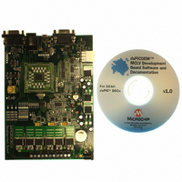
DM330021
Description
KIT DEMO DSPIC33 MCLV
Manufacturer
Microchip Technology
Series
dsPIC™r
Datasheet
1.DM330021.pdf
(40 pages)
Specifications of DM330021
Main Purpose
Power Management, Motor Control
Embedded
Yes, MCU, 16-Bit
Utilized Ic / Part
dsPIC33F
Primary Attributes
3-Ph BLDC or PMSM, 48V, 15A
Secondary Attributes
CAN, LIN, USB, RS-232 Interfaces
Processor To Be Evaluated
dsPIC33F
Interface Type
RS-232, USB
Lead Free Status / RoHS Status
Lead free / RoHS Compliant
Lead Free Status / RoHS Status
Lead free / RoHS Compliant, Lead free / RoHS Compliant
Available stocks
Company
Part Number
Manufacturer
Quantity
Price
Company:

Part Number:
DM330021
Manufacturer:
Microchip Technology
Quantity:
135
Company:
Part Number:
DM330021-2
Manufacturer:
MICROCHIP
Quantity:
12 000


dsPICDEM
2.3
TABLE 2-8:
2.4
FIGURE 2-2:
DS70331A-page 20
Note 1:
Remove the jumper
Remove the jumper
Install the jumper
Install the jumper
Note 1:
SELECTING A POWER SUPPLY FOR THE dsPICDEM MCLV DEVELOPMENT
BOARD
USER INTERFACE HARDWARE
JP1
When J3 is installed, VR3 must be removed to avoid damage to the 15V regulator.
J3
2:
Curr Volt
JUMPER SETTINGS FOR SELECTING A POWER SUPPLY
MONITOR_1
The JP1, JP2 and JP3 jumper pairs select the feedback signals required for the motor control algorithm.
The JP4 and JP5 jumper pairs select the communication bus for the transmit and receive pin.
The following connectors and power jumpers, when configured, offer multiple power
supply configuration options for the dsPICDEM MCLV Development Board.
• Input Power Connector (J2 or BP1-BP2)
• Bypass 15V Regulator (J3)
• DC Bus Power Supply Jumper (J6)
• Motor Power Connector with pins, ‘+’ and ‘-’ (J7)
To locate these components, refer to Figure 1-1. Table 2-8 describes how to select the
required power supply configuration option by setting jumper J3 and J6:
(1)
(1)
2.4.1
The dsPICDEM MCLV Development Board has nine jumpers that configure the
functionality of the board. Figure 2-2 shows the jumper settings and Table 2-9 lists
these jumpers and their functions.
JUMPER SETTINGS
TM
JP4
Hall
MCLV Development Board User’s Guide
USB
Remove the jumper
Remove the jumper
Jumpers
Install the jumper
Install the jumper
LIN CAN UART
Rx
J6
JP2
Curr Volt
MONITOR_2
J2 or BP1-BP2
JP5
16V to 24V
16V to 24V
10V to 16V
10V to 16V
Hall
USB
LIN CAN UART
Tx
JP3
Supplied by J2 or BP1-BP2
Supplied by J2 or BP1-BP2
Curr Volt
© 2008 Microchip Technology Inc.
MONITOR_3
J7: Pins ‘+’ and ‘-’
0V to 48V
0V to 48V
Hall
Related parts for DM330021
Image
Part Number
Description
Manufacturer
Datasheet
Request
R

Part Number:
Description:
Manufacturer:
Microchip Technology Inc.
Datasheet:
Part Number:
Description:
Manufacturer:
Microchip Technology Inc.
Datasheet:
Part Number:
Description:
Manufacturer:
Microchip Technology Inc.
Datasheet:
Part Number:
Description:
Manufacturer:
Microchip Technology Inc.
Datasheet:
Part Number:
Description:
Manufacturer:
Microchip Technology Inc.
Datasheet:
Part Number:
Description:
Manufacturer:
Microchip Technology Inc.
Datasheet:
Part Number:
Description:
Manufacturer:
Microchip Technology Inc.
Datasheet:
Part Number:
Description:
Manufacturer:
Microchip Technology Inc.
Datasheet: