OM11025 NXP Semiconductors, OM11025 Datasheet - Page 2
OM11025
Manufacturer Part Number
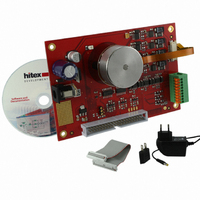
OM11025
Description
EXT BOARD MOTOR CONTROL LPC2900
Manufacturer
NXP Semiconductors
Datasheet
1.OM11025.pdf
(2 pages)
Specifications of OM11025
Main Purpose
Power Management, Motor Control
Embedded
Yes, MCU, 16/32-Bit
Utilized Ic / Part
LPC2900
Primary Attributes
Brushless DC (BLDC) & Bipolar Stepper Motors
Secondary Attributes
Graphical User Interface
Lead Free Status / RoHS Status
Lead free / RoHS Compliant
Other names
568-4786


Selector Guide
Third-Party Development Tools
Through third-party suppliers, we offer
a wide range of development tools
for our microcontrollers.
For the most up-to-date listing of
available evaluation boards, IDEs
and JTAG debuggers please visit
www.nxp.com/microcontrollers
On-The-Go/Device, 16 KB EEPROM,
UARTs with RS485 and LIN support,
Quadrature Encoder Interface and
Motor Control PWMs.
The LPC2900 series of microcontrollers
use the same peripherals as the
popular LPC2000 ARM7 family from
www.nxp.com
P/N
LPC2939
LPC2930
LPC2929
LPC2927
LPC2925
LPC2923
LPC2921
LPC2919/01
LPC2917/01
(KaB)
Flash
256
768
768
512
512
128
768
512
0
SRAM
©2008 NXP B.V.
All rights reserved. Reproduction in whole or in part is prohibited without the prior written consent of the copyright owner.
The information presented in this document does not form part of any quotation or contract, is believed to be accurate and
reliable and may be changed without notice. No liability will be accepted by the publisher for any consequence of its use.
Publication thereof does not convey nor imply any license under patent- or other industrial or intellectual property rights.
(KB)
56
56
56
56
40
24
24
56
56
TCM(KB)
32/32
32/32
32/32
32/32
I- /D-
16/16
16/16
16/16
16/16
16/16
EEPROM
(KB)
16
16
16
16
16
16
16
16
16
NXP, making it an easy upgrade option
for customers looking for additional
performance in a low cost embedded
system.
Additional features include dual CAN
interfaces, standard serial buses, plus a
sophisticated PWM and two 3.3V and
LPC2900 Block Diagram
USB Host/OTG/D
3.3 V ADC
SRAM
2 × 10-bit
48 KB
Up to 32 KB
Up to
2 × I
CAN
I-TCM
2
2
2
2
2
2
2
2
2
2
C
E
2
16 KB
LIN
PROM
2
2
2
2
2
2
2
2
2
Up to 32 KB
5 V ADC
Q-SPI
10-bit
D-TCM
UART
PHY
3 ×
4
4
4
4
4
4
4
2
2
768 KB
Up to
Flash
DMA
SPI
3
3
3
3
3
3
3
3
3
6 × 32-bit
2 × LIN
Timers
Advanced Peripheral Bus
Debug
Test/
Multi-layer AHB Matrix
ADC
ARM968E
3
3
3
3
2
2
2
2
2
Core
GP DMA
8 KB RAM
Trace +
EMI
Y
Y
Y
Y
Y
Y
one 5V analog to digital converters
(ADCs) that make the LPC2900
ideal for high-performance and
communication-heavy applications.
The family comes with up to 768 KB
embedded flash memory, 56 KB
RAM and 2x32 KB Tightly Coupled
Memories (TCM).
-
-
-
6 ch each
4 × PWM
Device
USB
RS485 support
Management
Y
Y
Y
Y
Y
Y
Y
-
-
Controller
2 × UARTs
Vectored
Interrupt
Power
Unit
Date of release: September 2008
Document order number: 9397 750 16628
Printed in the Netherlands
OTG
USB
External Memory Controller
Y
Y
Y
Y
-
-
-
-
-
Clock Generation Unit
Quadrature Encoder
Host
USB
Power On Reset
Y
Y
-
-
-
-
-
-
-
CPU PLL
Interface
Package
LQFP208
LQFP208
LQFP144
LQFP144
LQFP100
LQFP100
LQFP100
LQFP144
LQFP144
CAN2.0B
2 ×
Related parts for OM11025
Image
Part Number
Description
Manufacturer
Datasheet
Request
R

Part Number:
Description:
NXP Semiconductors designed the LPC2420/2460 microcontroller around a 16-bit/32-bitARM7TDMI-S CPU core with real-time debug interfaces that include both JTAG andembedded trace
Manufacturer:
NXP Semiconductors
Datasheet:

Part Number:
Description:
NXP Semiconductors designed the LPC2458 microcontroller around a 16-bit/32-bitARM7TDMI-S CPU core with real-time debug interfaces that include both JTAG andembedded trace
Manufacturer:
NXP Semiconductors
Datasheet:
Part Number:
Description:
NXP Semiconductors designed the LPC2468 microcontroller around a 16-bit/32-bitARM7TDMI-S CPU core with real-time debug interfaces that include both JTAG andembedded trace
Manufacturer:
NXP Semiconductors
Datasheet:
Part Number:
Description:
NXP Semiconductors designed the LPC2470 microcontroller, powered by theARM7TDMI-S core, to be a highly integrated microcontroller for a wide range ofapplications that require advanced communications and high quality graphic displays
Manufacturer:
NXP Semiconductors
Datasheet:
Part Number:
Description:
NXP Semiconductors designed the LPC2478 microcontroller, powered by theARM7TDMI-S core, to be a highly integrated microcontroller for a wide range ofapplications that require advanced communications and high quality graphic displays
Manufacturer:
NXP Semiconductors
Datasheet:
Part Number:
Description:
The Philips Semiconductors XA (eXtended Architecture) family of 16-bit single-chip microcontrollers is powerful enough to easily handle the requirements of high performance embedded applications, yet inexpensive enough to compete in the market for hi
Manufacturer:
NXP Semiconductors
Datasheet:
Part Number:
Description:
The XA-S3 device is a member of Philips Semiconductors? XA(eXtended Architecture) family of high performance 16-bitsingle-chip microcontrollers
Manufacturer:
NXP Semiconductors
Datasheet:

Part Number:
Description:
The NXP BlueStreak LH75401/LH75411 family consists of two low-cost 16/32-bit System-on-Chip (SoC) devices
Manufacturer:
NXP Semiconductors
Datasheet:
Part Number:
Description:
The NXP LPC3130/3131 combine an 180 MHz ARM926EJ-S CPU core, high-speed USB2
Manufacturer:
NXP Semiconductors
Datasheet:
Part Number:
Description:
The NXP LPC3141 combine a 270 MHz ARM926EJ-S CPU core, High-speed USB 2
Manufacturer:
NXP Semiconductors
Part Number:
Description:
The NXP LPC3143 combine a 270 MHz ARM926EJ-S CPU core, High-speed USB 2
Manufacturer:
NXP Semiconductors

Part Number:
Description:
The NXP LPC3152 combines an 180 MHz ARM926EJ-S CPU core, High-speed USB 2
Manufacturer:
NXP Semiconductors
Part Number:
Description:
The NXP LPC3154 combines an 180 MHz ARM926EJ-S CPU core, High-speed USB 2
Manufacturer:
NXP Semiconductors

Part Number:
Description:
Standard level N-channel enhancement mode Field-Effect Transistor (FET) in a plastic package using NXP High-Performance Automotive (HPA) TrenchMOS technology
Manufacturer:
NXP Semiconductors
Datasheet: