EVB9303 SMSC, EVB9303 Datasheet - Page 117
EVB9303
Manufacturer Part Number
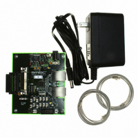
EVB9303
Description
EVALUATION BOARD FOR LAN9303
Manufacturer
SMSC
Specifications of EVB9303
Main Purpose
Interface, Ethernet
Embedded
No
Utilized Ic / Part
LAN9303
Primary Attributes
3 Ports, 100BASE-TX/10BASE-T, Managed
Secondary Attributes
Full Duplex and HP Auto-MDIX Support, 10BASE-T and 100BASE-TX
Lead Free Status / Rohs Status
Lead free / RoHS Compliant
Other names
638-1095


Small Form Factor Three Port 10/100 Managed Ethernet Switch with Single MII/RMII/Turbo MII
Datasheet
SMSC LAN9303/LAN9303i
8.4.6
8.4.7
8.5
Note: The starting address is a DWORD address. Appending two 0 bits will form the register address.
As an example, the following is a 3 burst sequence, with 1, 2, and 3 DWORDs starting at register
addresses 40h, 80h, and C0h respectively:
In order to avoid overwriting the Switch CSR register interface or the PHY Management Interface
(PMI), the EEPROM Loader waits until the
Interface Command Register (SWITCH_CSR_CMD)
Management Interface Access Register (PMI_ACCESS)
write.
The EEPROM Loader checks that the EEPROM address space is not exceeded. If so, it will stop and
set the
Register
of sizes. The address limit is set to the largest value of the specified range.
EEPROM Loader Finished Wait-State
Once finished with the last burst, the EEPROM Loader will go into a wait-state and the
Controller Busy (EPC_BUSY)
Reset Sequence and EEPROM Loader
In order to allow the EEPROM Loader to change the Port 1/2 PHYs and Virtual PHY strap inputs and
maintain consistency with the PHY and Virtual PHY registers, the following sequence is used:
1. After power-up or upon a hardware reset (nRST), the straps are sampled into the device as
2. After the PLL is stable, the main chip reset is released and the EEPROM Loader reads the
3. The EEPROM Loader writes select Port 1/2 and Virtual PHY registers, as specified in
Note: Step 3 is also performed in the case of a RELOAD command or digital reset.
When in MAC/PHY I
device. All system CSRs are accessible to the CPU in these modes. I
mngt_mode_strap[1:0]
implements the low level I
transmission and reception, and acknowledge generation and reception), handles the slave command
protocol, and performs system register reads and writes. The I
I
I
2
2
C-Bus Specification .
C Slave Operation
A5h, (Burst Sequence Valid Flag)
3h, (number_of_bursts)
16{10h, 1h}, (starting_address1 divided by 4 / count1)
11h, 12h, 13h, 14h, (4 x count1 of data)
16{20h, 2h}, (starting_address2 divided by 4 / count2)
21h, 22h, 23h, 24h, 25h, 26h, 27h, 28h, (4 x count2 of data)
16{30h, 3h}, (starting_address3 divided by 4 / count3)
31h, 32h, 33h, 34h, 35h, 36h, 37h, 38h, 39h, 3Ah, 3Bh, 3Ch (4 x count3 of data)
specified in
EEPROM and configures (overrides) the strap inputs.
Section 8.4.4.1
EEPROM Loader Address Overflow (LOADER_OVERFLOW)
(E2P_CMD). The address limit is based on the
Section 14.5.2, "Reset and Configuration Strap Timing," on page
and
2
C managed mode, the I
Section
configuration straps are set to 10b, respectively. The I
2
C slave serial interface (start and stop condition detection, data bit
bit of the
8.4.4.2, respectively.
DATASHEET
EEPROM Command Register (E2P_CMD)
117
CSR Busy (CSR_BUSY)
2
C slave interface is used for CPU management of the
and the
eeprom_size_strap
are cleared before performing any register
2
C slave controller conforms to the NXP
MII Busy (MIIBZY)
bit in the
2
bit of the
C mode is selected when the
which specifies a range
EEPROM Command
Revision 1.4 (07-07-10)
351.
Switch Fabric CSR
2
C slave controller
will be cleared.
bit of the
EEPROM
PHY
Related parts for EVB9303
Image
Part Number
Description
Manufacturer
Datasheet
Request
R


Part Number:
Description:
FAST ETHERNET PHYSICAL LAYER DEVICE
Manufacturer:
SMSC Corporation
Datasheet:
Part Number:
Description:
357-036-542-201 CARDEDGE 36POS DL .156 BLK LOPRO
Manufacturer:
SMSC Corporation
Datasheet:
Part Number:
Description:
357-036-542-201 CARDEDGE 36POS DL .156 BLK LOPRO
Manufacturer:
SMSC Corporation
Datasheet:
Part Number:
Description:
357-036-542-201 CARDEDGE 36POS DL .156 BLK LOPRO
Manufacturer:
SMSC Corporation
Datasheet:
Part Number:
Description:
4-PORT USB2.0 HUB CONTROLLER
Manufacturer:
SMSC Corporation
Datasheet:
Part Number:
Description:
Manufacturer:
SMSC Corporation
Datasheet:
Part Number:
Description:
Manufacturer:
SMSC Corporation
Datasheet:
Part Number:
Description:
FDC37C672ENHANCED SUPER I/O CONTROLLER WITH FAST IR
Manufacturer:
SMSC Corporation
Datasheet:
Part Number:
Description:
COM90C66LJPARCNET Controller/Transceiver with AT Interface and On-Chip RAM
Manufacturer:
SMSC Corporation
Datasheet:
Part Number:
Description:
Manufacturer:
SMSC Corporation
Datasheet:
Part Number:
Description:
Manufacturer:
SMSC Corporation
Datasheet:
Part Number:
Description:
Manufacturer:
SMSC Corporation
Datasheet:
Part Number:
Description:
Manufacturer:
SMSC Corporation
Datasheet: