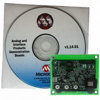
MCP1630DM-NMC1 Microchip Technology, MCP1630DM-NMC1 Datasheet - Page 12

MCP1630DM-NMC1
Manufacturer Part Number
MCP1630DM-NMC1
Description
BOARD DEMO FOR MCP1630
Manufacturer
Microchip Technology
Type
Battery Managementr
Datasheet
1.MCP1630DM-NMC1.pdf
(28 pages)
Specifications of MCP1630DM-NMC1
Main Purpose
Power Management, Battery Charger
Embedded
Yes, MCU, 8-Bit
Utilized Ic / Part
MCP1630
Primary Attributes
4 Cells- NiMH, 500mA, 8 V ~ 15 V Input
Secondary Attributes
Simple Fuel Gauge, 3 Charge Modes, Over: Current/Voltage/Charge Protection
Product
Power Management Modules
For Use With/related Products
MCP1630
Lead Free Status / RoHS Status
Contains lead / RoHS non-compliant
Lead Free Status / RoHS Status
Lead free / RoHS Compliant, Contains lead / RoHS non-compliant
MCP1630 NiMH Battery Charger Demo Board User’s Guide
2.3
DS51505B-page 8
GETTING STARTED
The MCP1630 NiMH Battery Charger Demo Board is fully assembled and tested for
charging four 1,000 mA/hour NiMH batteries in series from 3.2V to 6V in accordance
with the recommended charge profile for NiMH batteries. This board requires the use
of an external input voltage source (+8V to +15V) and external load (battery or simu-
lated battery load). It is recommended that four NiMH cells connected in series to act
as a load or the recommended simulated load be used.
2.3.1
2.3.1.1
1. Apply the input voltage to the surface mount test points provided. The input
2. Connect the positive side of the input source (+) to test point TP2. Connect the
2.3.1.2
1. To apply a load to the MCP1630 NiMH Battery Charger Demo Board, the positive
2. The code will prevent the board from entering the 500 mA Fast Charge mode if
FIGURE 2-1:
voltage source should be limited to the 0V to +15V range. For normal operation,
the input voltage should be between +8V and +15V. However, the input voltage
must not exceed +15V maximum. The source current necessary to regulate the
output voltage to 6.4V at 500 mA should be a minimum of approximately 800 mA.
negative (or return side) (–) of the input source to the GND test point TP3. TP2
is located just above TP3 in the upper-left corner of the board.
side of the load (+) should be connected to test point TP1. The negative side of
the load (–) should be connected to test point TP4. Care should be taken when
using electronic or ground-referenced loads, and never connect TP4 to ground.
The battery current sense is referenced in the return leg, so connecting TP4 to
ground will short out the current sense. The typical charge current is 50 mA while
the battery is in the Trickle Charge mode or the battery voltage is below 0.8V/cell.
The current is typically 500 mA when the battery is in the Fast Charge mode and
typically 25 mA when the battery is in the Top-off Charge mode. The charge
current is automatically regulated by the MCP1630.
the battery terminal voltage is less than 3.2V (0.8V / Cell). During power up, the
board will always trickle charge first, so using a purely resistive load will not work
for trickle and fast charge currents. The best way to evaluate the charger is to
use four series NiMH batteries or the recommended simulated battery load.
+
–
Charger
Power Input and Output Connections
POWERING THE MCP1630 NiMH BATTERY CHARGER DEMO BOARD.
APPLYING THE LOAD TO THE MCP1630 NiMH BATTERY CHARGER
DEMO BOARD.
TP1
TP4
Simulated Battery Load.
+
–
1,000 μF
10V Al
10Ω
5 Watt
© 2006 Microchip Technology Inc.
+
–
4V Lab Supply


