RDK-128 Power Integrations, RDK-128 Datasheet - Page 16
RDK-128
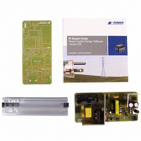
Manufacturer Part Number
RDK-128
Description
KIT REF DESIGN 36-72W MOTOR DRVR
Manufacturer
Power Integrations
Specifications of RDK-128
Main Purpose
Power Management, Motor Control
Embedded
No
Utilized Ic / Part
PKS606
Primary Attributes
Variable Speed 12V 36W DC Motor, 90 ~ 265 VAC
Secondary Attributes
External Potentiometer or Variable DC Voltage Speed Control
Lead Free Status / RoHS Status
Not applicable / Not applicable
Other names
596-1198


NOTES:
A. Total current consumption is the sum of I
B. Since the output MOSFET is switching, it is difficult to isolate the switching current from the supply current at the
C. See Typical Performance Characteristics section for BYPASS pin startup charging waveform.
D. BYPASS pin is externally supplied (bias winding).
E. For current limit at other di/dt values, refer to Figure 25.
F. This parameter is derived from characterization.
G. This parameter is derived from the change in current limit measured at 1X and 4X of the di/dt shown in the I
H. I
I. Breakdown voltage may be checked against minimum BV
J. Auto-restart on time has the same temperature characteristics as the oscillator (inversely proportional to
K. Only applicable if no UV resistor is present at the EN/UV pin. 5 s applies only if the preceding switching auto-
Rev. I 02/07
OUTPUT (cont.)
Auto-Restart
ON Time
Auto-Restart
OFF Time
16
switching) and the sum of I
DRAIN. An alternative is to measure the BYPASS pin current at 6.1 V.
temperature. I
consumption calculations.
to but not exceeding minimum BV
frequency). Auto-restart on time is extended during startup and certain fault conditions because the controller
reduces its oscillator clock frequency to prevent excessive drain currents. If excessive drain currents are still
occuring half way through the auto-restart on time, output MOSFET switching is disabled for the remainder of that
auto-restart on time episode (if the line is not sensed) or the supply latches off (if the line is sensed and adequate
line voltage is present).
restart event did not result in EN/UV pin going low. In that event, the first auto-restart off-time is 150 ms.
specification.
DSS1
Parameter
is the worst case OFF state leakage specification at 80% of BV
PKS603-607
DSS2
is a typical specification under worst case application conditions (rectified 265 VAC) for no-load
Symbol
t
AROFF
t
AR
S2
and I
DSS
DSS
SOURCE = 0 V; T
.
when EN/UV pin is open (MOSFET switching).
(Unless Otherwise Specified)
S1
and I
Conditions
See Figure 18
See Note K
See Note J
T
DSS
J
= 25 °C
when EN/UV pin is shorted to ground (MOSFET not
J
= -40 to 125 °C
DSS
specification by ramping the DRAIN pin voltage up
DSS
and maximum operating junction
Min
Typ
30
5
Max
Units
ms
LIMIT
s
Related parts for RDK-128
Image
Part Number
Description
Manufacturer
Datasheet
Request
R

Part Number:
Description:
KIT REF DESIGN FOR LNK457D
Manufacturer:
Power Integrations
Datasheet:

Part Number:
Description:
REFERENCE DESIGN LINKSWITCH-PH
Manufacturer:
Power Integrations
Datasheet:

Part Number:
Description:
KIT REF DESIGN FOR LNK403EG
Manufacturer:
Power Integrations
Datasheet:

Part Number:
Description:
KIT REF DESIGN FOR LNK406EG
Manufacturer:
Power Integrations
Datasheet:

Part Number:
Description:
KIT REF DESIGN LINKSWITCH-CV
Manufacturer:
Power Integrations
Datasheet:

Part Number:
Description:
KIT REF DESIGN LINKSWITCH 2
Manufacturer:
Power Integrations
Datasheet:

Part Number:
Description:
Specifications: Family: Eval Boards - DC/DC & AC/DC (Off-Line) SMPS ; Series: HiperLCS™ ; Main Purpose: DC/DC, Step Down ; Outputs and Type: 1, Isolated ; Power - Output: 150W ; Voltage - Output: 24V ; Current - Output: 6.25A ; Voltage - Input:
Manufacturer:
Power Integrations, Inc.
Datasheet:

Part Number:
Description:
KIT DESIGN REF TINYSWITCH-III
Manufacturer:
Power Integrations
Datasheet:

Part Number:
Description:
KIT DESIGN REF LINKSWITCH LP
Manufacturer:
Power Integrations
Datasheet:

Part Number:
Description:
KIT REF DESIGN LED LINKSWITCH TN
Manufacturer:
Power Integrations
Datasheet:
Part Number:
Description:
KIT REF DESIGN FOR LNK457D
Manufacturer:
Power Integrations
Datasheet:
Part Number:
Description:
REFERENCE DESIGN LINKSWITCH-PH
Manufacturer:
Power Integrations
Datasheet:
Part Number:
Description:
Specifications: Manufacturer: Power Integrations ; Output Voltage: 380 VDC ; Input / Supply Voltage (Max): 264 VAC ; Input / Supply Voltage (Min): 90 VAC ; Mounting Style: Through Hole ; Output Current: 0.913 A ; Output Power: 347 W
Manufacturer:
Power Integrations, Inc.
Part Number:
Description:
Specifications: Family: Eval Boards - DC/DC & AC/DC (Off-Line) SMPS ; Series: HiperLCS™ ; Main Purpose: DC/DC, Step Down ; Outputs and Type: 1, Isolated ; Power - Output: 150W ; Voltage - Output: 24V ; Current - Output: 6.25A ; Voltage - Input:
Manufacturer:
Power Integrations, Inc.
Datasheet: