CDB5571 Cirrus Logic Inc, CDB5571 Datasheet - Page 13
CDB5571
Manufacturer Part Number
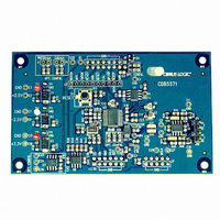
CDB5571
Description
DEV BOARD FOR CS5571 W/MUX
Manufacturer
Cirrus Logic Inc
Type
A/Dr
Specifications of CDB5571
Number Of Adc's
1
Number Of Bits
16
Sampling Rate (per Second)
100k
Data Interface
Serial
Inputs Per Adc
2 Single
Input Range
2.4 ~ 4.2 V
Voltage Supply Source
Dual ±
Operating Temperature
-40°C ~ 85°C
Utilized Ic / Part
CS5571
Product
Data Conversion Development Tools
Conversion Rate
100 KSPS
Resolution
16 bit
Maximum Clock Frequency
16 MHz
Interface Type
SPI
Supply Voltage (max)
3.3 V
Supply Voltage (min)
- 2.5 V
For Use With/related Products
CS5571
Lead Free Status / RoHS Status
Contains lead / RoHS non-compliant
Lead Free Status / RoHS Status
Lead free / RoHS Compliant, Contains lead / RoHS non-compliant
Other names
598-1275
CDB5571-1
CDB5571-1


3/25/08
CS5571
10:56
2. OVERVIEW
The CS5571 is a 16-bit analog-to-digital converter capable of 100 kSps conversion rate. The analog input
accepts a single-ended input with a magnitude of ±VREF / 2
The device is capable of switching mul-
volts.
tiple input channels at a high rate with no loss in throughput. The ADC uses a low-latency digital filter ar-
chitecture. The filter is designed for fast settling and settles to full accuracy in one conversion.
The converter is a serial output device. The serial port can be configured to function as either a master or
a slave.
The converter can operate from an analog supply of 5V or from ±2.5V. The digital interface supports stan-
dard logic operating from 1.8, 2.5, or 3.3 V.
The CS5571 may convert at rates up to 100 kSps when operating from a 16 MHz input clock.
3. THEORY OF OPERATION
The CS5571 converter provides high-performance measurement of DC or AC signals. The converter can
be used to perform single conversions or continuous conversions upon command. Each conversion is in-
dependent of previous conversions and settles to full specified accuracy, even with a full-scale input volt-
age step. This is due to the converter architecture which uses a combination of a high-speed delta-sigma
modulator and a low-latency filter architecture.
Once power is established to the converter, a reset must be performed. A reset initializes the internal con-
verter
logic.
If CONV is held low, the converter will convert continuously with RDY falling every 160 MCLKs. This is
equivalent to 100 kSps if MCLK = 16.0 MHz. If CONV is tied to RDY, a conversion will occur every 162
MCLKs. If CONV is operated asynchronously to MCLK, it may take up to 164 MCLKs from CONV falling
to RDY falling.
Multiple converters can operate synchronously if they are driven by the same MCLK source and CONV
to each converter falls on the same MCLK falling edge. Alternately, CONV can be held low and all devices
can be synchronized if they are reset with RST rising on the same falling edge of MCLK.
The output coding of the conversion word is a function of the BP/UP pin.
3.1 Converter Operation
The converter should be reset after the power supplies and voltage reference are stable.
The CS5571 converts at 100 kSps when synchronously operated (CONV = VLR) from a 16.0 MHz master
clock. Conversion is initiated by taking CONV low. A conversion lasts 160 master clock cycles, but if
CONV is asynchronous to MCLK there may be an uncertainty of 0-4 MCLK cycles after CONV falls to
when a conversion actually begins. This may extend the throughput to 164 MCLKs per conversion.
When the conversion is completed, the output word is placed into the serial port and RDY goes low. To
convert continuously, CONV should be held low. In continuous conversion mode with CONV held low, a
conversion is performed in 160 MCLK cycles. Alternately RDY can be tied to CONV and a conversion will
occur every 162 MCLK cycles.
To perform only one conversion, CONV should return high at least 20 master clock cycles before RDY
falls.
DS768PP1
13
Related parts for CDB5571
Image
Part Number
Description
Manufacturer
Datasheet
Request
R

Part Number:
Description:
Development Kit
Manufacturer:
Cirrus Logic Inc
Datasheet:
Part Number:
Description:
Development Kit
Manufacturer:
Cirrus Logic Inc
Datasheet:


Part Number:
Description:
High-efficiency PFC + Fluorescent Lamp Driver Reference Design
Manufacturer:
Cirrus Logic Inc
Datasheet:
Part Number:
Description:
Development Kit
Manufacturer:
Cirrus Logic Inc
Datasheet:
Part Number:
Description:
Development Kit
Manufacturer:
Cirrus Logic Inc
Datasheet:

Part Number:
Description:
Development Kit
Manufacturer:
Cirrus Logic Inc
Datasheet:
Part Number:
Description:
Development Kit
Manufacturer:
Cirrus Logic Inc
Datasheet:
Part Number:
Description:
Development Kit
Manufacturer:
Cirrus Logic Inc
Datasheet:
Part Number:
Description:
Development Kit
Manufacturer:
Cirrus Logic Inc
Datasheet:

Part Number:
Description:
EVALUATION BOARD FOR CS8427
Manufacturer:
Cirrus Logic Inc
Datasheet:

Part Number:
Description:
BOARD EVAL FOR CS8416 RCVR
Manufacturer:
Cirrus Logic Inc
Datasheet:

Part Number:
Description:
EVALUATION BOARD FOR CS8420
Manufacturer:
Cirrus Logic Inc
Datasheet:

Part Number:
Description:
KIT DEVELOPMENT EP9315 ARM9
Manufacturer:
Cirrus Logic Inc
Datasheet:

Part Number:
Description:
KIT DEVELOPMENT EP9302 ARM9
Manufacturer:
Cirrus Logic Inc
Datasheet: