SSM2305-EVALZ Analog Devices Inc, SSM2305-EVALZ Datasheet
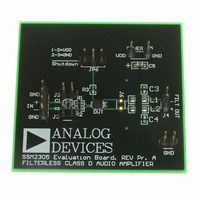
SSM2305-EVALZ
Specifications of SSM2305-EVALZ


Related parts for SSM2305-EVALZ


SSM2305-EVALZ Summary of contents
Page 1
... The SSM2305 has excellent rejection of power supply noise, including noise caused by GSM transmission bursts and RF rectification. PSRR is typically 217 Hz. The default gain of the SSM2305 is 18 dB, but users can reduce the gain by using a pair of external resistors. The SSM2305 is specified over the commercial temperature range (− ...
Page 2
... SSM2305 TABLE OF CONTENTS Features .............................................................................................. 1 Applications ....................................................................................... 1 General Description ......................................................................... 1 Functional Block Diagram .............................................................. 1 Revision History ............................................................................... 2 Specifications ..................................................................................... 3 Absolute Maximum Ratings ............................................................ 4 Thermal Resistance ...................................................................... 4 ESD Caution .................................................................................. 4 Pin Configurations and Function Descriptions ........................... 5 Typical Performance Characteristics ............................................. 6 REVISION HISTORY 7/08—Rev Rev. A Changes to Figure 1 .......................................................................... 1 Change to Shutdown Current Parameter, Table 1 ........................ 3 Change to Differential Input Impedance Parameter, Table 1 ...
Page 3
... Rev Page Min Typ 1.34 = 3.6 V 0.68 DD 1.67 = 3.6 V 0.85 DD 2.22 = 3.6 V 1.1 DD 2.8 = 3 0.02 = 3.6 V 0.02 DD 1.0 55 280 2.0 2 0.1 μ 3.2 3.3 2.8 2.9 2.4 2 1.2 0 >100 40 98 SSM2305 Max Unit − kHz mV 5 kΩ μs kΩ μV dB ...
Page 4
... SSM2305 ABSOLUTE MAXIMUM RATINGS Absolute maximum ratings apply wise noted. Table 2. Parameter Supply Voltage Input Voltage Common-Mode Input Voltage Storage Temperature Range Operating Temperature Range Junction Temperature Range Lead Temperature (Soldering, 60 sec) Stresses above those listed under Absolute Maximum Ratings may cause permanent damage to the device. This is a stress rating only ...
Page 5
... Shutdown Input. Active low digital input. No Connect. This pin has no function; tie it to GND. Noninverting Input. Inverting Input. Noninverting Output. Power Supply. Ground. Inverting Output. Rev Page SSM2305 SD OUT– SSM2305 NC GND 2 7 TOP VIEW IN+ VDD 3 6 (Not to Scale) IN– OUT+ 4 ...
Page 6
... SSM2305 TYPICAL PERFORMANCE CHARACTERISTICS 100 R = 4Ω + 33µH L GAIN = 18dB 0.1 0.01 0.0001 0.001 0.01 0.1 OUTPUT POWER (W) Figure 4. THD + N vs. Output Power into 4 Ω μH, A 100 R = 4Ω + 33µH L GAIN = 6dB 2. 3. 0.1 0.01 0.001 0.001 0.0001 0.01 0.1 OUTPUT POWER (W) Figure 5. THD + N vs. Output Power into 4 Ω ...
Page 7
... L 3 8Ω + 33µH L 2.8 NO LOAD 2.6 2.4 2.2 2.0 2.5 3.0 3.5 4.0 4.5 5.0 SUPPLY VOLTAGE (V) Figure 14. Supply Current vs. Supply Voltage 2. 0.1 0.2 0.3 0.4 0.5 0.6 SHUTDOWN VOLTAGE (V) Figure 15. Shutdown Current vs. Shutdown Voltage SSM2305 100000 = 5 3.6V 0.7 0.8 ...
Page 8
... SSM2305 3 1kHz GAIN = 18dB 2 4Ω + 33µH L 2.0 10% 1.5 1% 1.0 0.5 0 2.5 3.0 3.5 4.0 SUPPLY VOLTAGE (V) Figure 16. Maximum Output Power vs. Supply Voltage Ω μ 3 1kHz GAIN = 6dB 2 4Ω + 33µH L 2.0 10% 1.5 1% 1.0 0.5 0 2.5 3.0 3.5 4.0 SUPPLY VOLTAGE (V) Figure 17 ...
Page 9
... Figure 26. Supply Current vs. Output Power into 4 Ω μH 450 400 350 300 250 200 150 100 50 0 1.2 1.4 1.6 0 Figure 27. Supply Current vs. Output Power into 8 Ω μH Rev Page SSM2305 8Ω + 33µH L 0.1 0.2 0.3 0.4 0.5 0.6 0.7 0.8 OUTPUT POWER ( ...
Page 10
... SSM2305 0 –10 –20 –30 –40 –50 –60 –70 –80 –90 –100 10 100 1000 FREQUENCY (Hz) Figure 28. Power Supply Rejection Ratio vs. Frequency 0 –10 –20 –30 –40 –50 –60 –70 –80 –90 –100 10 100 1000 FREQUENCY (Hz) Figure 29. Common-Mode Rejection Ratio vs. Frequency 10000 100000 10000 100000 Rev ...
Page 11
... Most Class-D amplifiers use some variation of pulse-width modulation (PWM), but the SSM2305 uses Σ-Δ modulation to determine the switching pattern of the output devices, resulting in a number of EXTERNAL GAIN SETTINGS = 296kΩ/(37kΩ AUDIO IN+ AUDIO IN– ...
Page 12
... SSM2305 GAIN The SSM2305 has a default gain that can be reduced by using a pair of external resistors with a value calculated as follows: External Gain Settings = 296 kΩ/(37 kΩ POP-AND-CLICK SUPPRESSION Voltage transients at the output of audio amplifiers can occur when shutdown activates or deactivates. Voltage transients as low can be heard as audio pops in the speaker ...
Page 13
... ESL, low ESR capacitor, usually of around 4.7 μF. This capacitor bypasses low frequency noises to the ground plane. For high frequency transient noise, use a 0.1 μF capacitor as close as possible to the VDD pin of the device. Placing the decoupling capacitor as close as possible to the SSM2305 helps maintain efficient performance. Rev Page SSM2305 ...
Page 14
... SSM2305CPZ-REEL7 −40°C to +85°C 1 SSM2305RMZ-R2 −40°C to +85°C 1 SSM2305RMZ-REEL −40°C to +85°C 1 SSM2305RMZ-REEL7 −40°C to +85°C 1 SSM2305-EVALZ RoHS Compliant Part. 3.25 0.60 MAX 3.00 SQ 2.75 0.60 MAX 5 2.95 EXPOSED 2.75 SQ TOP PAD VIEW 2 ...
Page 15
... NOTES Rev Page SSM2305 ...
Page 16
... SSM2305 NOTES ©2008 Analog Devices, Inc. All rights reserved. Trademarks and registered trademarks are the property of their respective owners. D07243-0-7/08(A) Rev Page ...