EVALTSM1052 STMicroelectronics, EVALTSM1052 Datasheet - Page 6
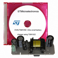
EVALTSM1052
Manufacturer Part Number
EVALTSM1052
Description
BOARD EVAL FOR TSM1052
Manufacturer
STMicroelectronics
Series
VIPER™r
Type
Battery Managementr
Datasheet
1.EVALTSM1052.pdf
(21 pages)
Specifications of EVALTSM1052
Main Purpose
AC/DC, Primary and Secondary Side
Outputs And Type
1, Isolated
Power - Output
3W
Voltage - Output
5.1V
Current - Output
600mA
Voltage - Input
90 ~ 264VAC
Regulator Topology
Flyback
Frequency - Switching
60kHz
Board Type
Fully Populated
Utilized Ic / Part
TSM1052, VIPer12A
Input Voltage
90 V to 264 V
Output Voltage
5.1 V
Board Size
48 mm x 18 mm
Product
Power Management Modules
Dimensions
48 mm x 18 mm
Silicon Manufacturer
ST Micro
Silicon Core Number
TSM1052
Kit Application Type
Power Management - Battery
Application Sub Type
Battery Charger
Kit Contents
Board
Lead Free Status / RoHS Status
Lead free / RoHS Compliant
For Use With/related Products
TSM1052
Other names
497-6242
Available stocks
Company
Part Number
Manufacturer
Quantity
Price


Adapter features
1.2
6/21
Circuit description
The circuit used implements a flyback topology, which is ideal for a low power, low cost
isolated converter.
At primary side a VIPer12A-E has been used. This IC includes a current mode PWM
controller and a Power MOSFET in a small SO-8 package. The converter works in both
continuous and discontinuous conduction mode depending on the input voltage (the circuit
has a wide range input) and the output load. The switching frequency is internally fixed at 60
KHz. The design has been developed to reduce overall component count and adapter cost.
The input section includes a resistor for inrush current limiting, a diode bridge, two
electrolytic bulk capacitors and an inductor as front-end ac-dc converter and EMC filter. The
transformer is a layer type, uses a standard EF12.6 ferrite core and is designed to have a
reflected voltage of about 90 V. The peculiarity of this transformer is the winding technique
which allows the elimination of the usual Y1 safety capacitor between the primary and the
secondary. A RCD clamp network is used for leakage inductance demagnetization. The
power supply for the VIPer12A-E is obtained with a self supply winding from the transformer
connected in forward configuration. This circuit provides a voltage that is directly
proportional to the input rectified voltage and independent from the load voltage. In this way
even in short circuit condition (V
operating range (9 V to 38 V) of the VIPer12A-E allows a wide range mains input voltage.
At secondary side, the TSM1052 constant voltage constant current (CVCC) controller is
used. Like the VIPer12A-E, the TSM1052 is also supplied with a forward configuration, in
order to obtain the same benefit. The voltage is taken on one half of the secondary winding
(between pins 8 and 6), rectified with diode D5 and added to the output voltage. Under all
working conditions, the voltage supply for the TSM1052 and the photodiode IC1B is equal to
the output voltage plus forward rectified voltage on half secondary. With this configuration a
correct supply is provided over the whole input range, even with the output short circuited.
With this configuration a small ripple at twice line frequency is present at the output. This is
due to the supply of the photodiode IC1B, which is a replica of the voltage on C2. Usually
this is not a problem in battery chargers. There are two ways to eliminate this phenomenon
if necessary:
●
●
Resistor R7 has been added for cable drop compensation (the higher the output current the
higher the output voltage). R7 has been chosen according to the cable characteristics (it has
about 0.3 Ω of resistance).
C9 can be substituted by an electrolytic capacitor (at least 47 µF)
The TSM1052 and IC1B can be attached directly to the output voltage. In this case the
current regulation is guaranteed only for output voltages down to 1.7 V
OUT
= 0), the IC is correctly supplied. The wide V
DD
AN2448
Related parts for EVALTSM1052
Image
Part Number
Description
Manufacturer
Datasheet
Request
R

Part Number:
Description:
ENERCHIP CC EVAL KIT
Manufacturer:
Cymbet Corporation
Datasheet:

Part Number:
Description:
BOARD EVAL FOR AD976
Manufacturer:
Analog Devices Inc
Datasheet:

Part Number:
Description:
BOARD EVAL FOR ADXL345
Manufacturer:
Analog Devices Inc
Datasheet:

Part Number:
Description:
ENERCHIP CC SEH EVAL KIT
Manufacturer:
Cymbet Corporation
Datasheet:

Part Number:
Description:
ENERCHIP EP ENERGY HARVEST EVAL
Manufacturer:
Cymbet Corporation
Datasheet:

Part Number:
Description:
EVAL BOARD FOR TW6864-LB2-GR
Manufacturer:
Intersil
Datasheet:
Part Number:
Description:
EVAL BOARD FOR TW8816-LB3-GR
Manufacturer:
Intersil
Datasheet:
Part Number:
Description:
EVAL BOARD FOR TW8817-TA3-GRS
Manufacturer:
Intersil
Datasheet:

Part Number:
Description:
EVALUATION MODULE FOR ADUM4160
Manufacturer:
Analog Devices Inc
Datasheet:

Part Number:
Description:
BOARD EVALUATION ADCMP581BCP
Manufacturer:
Analog Devices Inc
Datasheet:
Part Number:
Description:
BOARD EVALUATION ADM1041
Manufacturer:
Analog Devices Inc
Datasheet:

Part Number:
Description:
EVAL BOARD FOR STM32F107VCT
Manufacturer:
STMicroelectronics
Datasheet:
Part Number:
Description:
BOARD EVAL FOR AD1954
Manufacturer:
Analog Devices Inc
Datasheet:
Part Number:
Description:
BOARD EVAL FOR AD1955
Manufacturer:
Analog Devices Inc
Datasheet:

Part Number:
Description:
BOARD EVAL FOR AD7655
Manufacturer:
Analog Devices Inc
Datasheet: