STEVAL-ISA006V1 STMicroelectronics, STEVAL-ISA006V1 Datasheet - Page 11
STEVAL-ISA006V1
Manufacturer Part Number
STEVAL-ISA006V1
Description
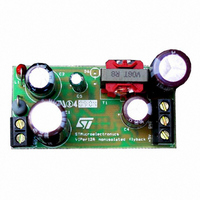
EVAL BOARD FLYBACK PWR SUPPLY 6W
Manufacturer
STMicroelectronics
Series
VIPER™r
Type
DC/DC Switching Converters, Regulators & Controllersr
Specifications of STEVAL-ISA006V1
Mfg Application Notes
VIPer12A Non-Isolated Flyback Converter
Design Resources
STEVAL-ISA006V1 Gerber Files STEVAL-ISA006V1 Schematic STEVAL-ISA006V1 Bill of Materials
Main Purpose
AC/DC, Non-Isolated
Outputs And Type
2, Non-Isolated
Power - Output
5.5W
Voltage - Output
5V, 15V
Current - Output
500mA, 200mA
Voltage - Input
90 ~ 264VAC
Regulator Topology
Flyback
Frequency - Switching
60kHz
Board Type
Fully Populated
Utilized Ic / Part
VIPer12A
Input Voltage
90 V to 264 V
Output Voltage
5 V, 15 V
Product
Power Management Modules
Silicon Manufacturer
ST Micro
Silicon Core Number
VIPer12AS
Kit Application Type
Power Management
Application Sub Type
Power Supply
Kit Contents
Board
Rohs Compliant
No
Lead Free Status / RoHS Status
Contains lead / RoHS non-compliant
For Use With/related Products
VIPer12AS
Other names
497-5082


VIPER12A-E
7
Startup sequence
Figure 7.
This device includes a high voltage start up current source connected on the drain of the
device. As soon as a voltage is applied on the input of the converter, this start up current
source is activated as long as V
current source is switched off and the device begins to operate by turning on and off its main
power MOSFET. As the FB pin does not receive any current from the optocoupler, the
device operates at full current capacity and the output voltage rises until reaching the
regulation point where the secondary loop begins to send a current in the optocoupler. At
this point, the converter enters a regulated operation where the FB pin receives the amount
of current needed to deliver the right power on secondary side.
This sequence is shown in
consumes some energy from the V
continuous supply. If the value of this capacitor is too low, the start up phase is terminated
before receiving any energy from the auxiliary winding and the converter never starts up.
This is illustrated also in the same figure in dashed lines.
Startup sequence
Figure
Doc ID 11977 Rev 2
DD
7. Note that during the real starting phase t
DD
is lower than V
capacitor, waiting for the auxiliary winding to provide a
DDon
. When reaching V
Startup sequence
DDon
ss
, the start up
, the device
11/21
Related parts for STEVAL-ISA006V1
Image
Part Number
Description
Manufacturer
Datasheet
Request
R

Part Number:
Description:
BOARD RGB CTR ST7,STP08C596MTR
Manufacturer:
STMicroelectronics
Datasheet:

Part Number:
Description:
Power Management IC Development Tools Full Speed USB to RS232 Bridge Demo
Manufacturer:
STMicroelectronics
Datasheet:
Part Number:
Description:
Power Management IC Development Tools 2.5W solar eval BRD USB SPV1040 LD39050
Manufacturer:
STMicroelectronics
Datasheet:

Part Number:
Description:
BOARD EVAL FOR MEMS SENSORS
Manufacturer:
STMicroelectronics
Datasheet:

Part Number:
Description:
KIT DEV STARTER ST10F276Z5
Manufacturer:
STMicroelectronics
Datasheet:

Part Number:
Description:
BOARD EVAL HDMI $ VIDEO SWITCH
Manufacturer:
STMicroelectronics
Datasheet:

Part Number:
Description:
BOARD DEMO ACCELEROMETER DIL24
Manufacturer:
STMicroelectronics
Datasheet:

Part Number:
Description:
BOARD STLM75/STDS75/ST72F651
Manufacturer:
STMicroelectronics
Datasheet:

Part Number:
Description:
EVAL BOARD 3AXIS MEMS ACCELLRMTR
Manufacturer:
STMicroelectronics
Datasheet:

Part Number:
Description:
BOARD EVAL 8BIT MICRO + TDE1708
Manufacturer:
STMicroelectronics
Datasheet:
Part Number:
Description:
STMicroelectronics [RIPPLE-CARRY BINARY COUNTER/DIVIDERS]
Manufacturer:
STMicroelectronics
Datasheet:
Part Number:
Description:
STMicroelectronics [LIQUID-CRYSTAL DISPLAY DRIVERS]
Manufacturer:
STMicroelectronics
Datasheet:
Part Number:
Description:
BOARD EVAL FOR MEMS SENSORS
Manufacturer:
STMicroelectronics
Datasheet: