BG2D Powerex Inc, BG2D Datasheet - Page 5
BG2D
Manufacturer Part Number
BG2D
Description
KIT DESIGN FOR NX SERIES IGBT
Manufacturer
Powerex Inc
Series
NXr
Datasheet
1.BG2D.pdf
(6 pages)
Specifications of BG2D
Main Purpose
DC/DC, Step Down
Regulator Topology
Buck
Board Type
Bare (Unpopulated)
Lead Free Status / RoHS Status
Lead free / RoHS Compliant
Current - Output
-
Voltage - Output
-
Voltage - Input
-
Power - Output
-
Utilized Ic / Part
-
Frequency - Switching
-
Outputs And Type
-
Other names
835-1066


25°C can be easily measured. It is important to note that this equation is valid for temperatures measured in
Kelvin (K) in which case T
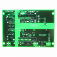
Printed Circuit Layout: Figure 5 shows the layout of the BG2D two channel gate driver board. The compact 3”
x 2.2” circuit board with only 28 components clearly demonstrates the advantage of using hybrid gate drivers
and DC to DC converters. One important feature is the use of three ground plane islands for the regions of the
PCB having high voltage differences. Two of the islands are tied to the IGBT emitter/circuit common (Pin 2 of
the DC to DC converters) of each output channel. The third island is connected to logic interface common at pin
6 of CN1. This layout provides shielding to help prevent undesirable coupling of noise between the control side
and the gate drive channels.
Additional Information: Detailed information about the operation and electrical characteristics of the M57159L-
01, VLA503-01 and VLA-504-01 hybrid gate drivers can be found on the individual device data sheets. Electrical
characteristics such as input voltage range, efficiency, and output voltage regulation of the VLA106-15242 and
VLA106-24242 DC to DC converters can also be found on the individual device data sheets. Information about
calculating gate drive current and selection of series gate resistors (R
module and gate drive application notes. For applications using higher current IGBT modules refer to the
application notes for the VLA500-01 hybrid gate driver and BG2A reference design. For applications using high
frequency optimized NFH series IGBT modules refer to the VLA502-01 application note. All of these documents
25
= 25+273 = 298K.
EQ.1: B = (lnR
EQ.2: T
x
= B / (lnR
5
1
– lnR
x
– lnR
2
) / (1/T
25
) + T
1
-1/T
G
) can be found in the general IGBT
25
2
)
Related parts for BG2D
Image
Part Number
Description
Manufacturer
Datasheet
Request
R

Part Number:
Description:
Manufacturer:
Powerex Inc
Datasheet:
Part Number:
Description:
Manufacturer:
Powerex Inc
Datasheet:
Part Number:
Description:
Manufacturer:
Powerex Inc
Datasheet:
Part Number:
Description:
Manufacturer:
Powerex Inc
Datasheet:
Part Number:
Description:
Manufacturer:
Powerex Inc
Datasheet:
Part Number:
Description:
Manufacturer:
Powerex Inc
Datasheet:
Part Number:
Description:
Manufacturer:
Powerex Inc
Datasheet:
Part Number:
Description:
Manufacturer:
Powerex Inc
Datasheet:
Part Number:
Description:
Manufacturer:
Powerex Inc
Datasheet:
Part Number:
Description:
Manufacturer:
Powerex Inc
Datasheet:
Part Number:
Description:
Manufacturer:
Powerex Inc
Datasheet:
Part Number:
Description:
Manufacturer:
Powerex Inc
Datasheet:
Part Number:
Description:
Manufacturer:
Powerex Inc
Datasheet:
Part Number:
Description:
Manufacturer:
Powerex Inc
Datasheet: