NCP1014STBUCGEVB ON Semiconductor, NCP1014STBUCGEVB Datasheet
NCP1014STBUCGEVB
Manufacturer Part Number
NCP1014STBUCGEVB
Description
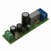
EVAL BOARD FOR NCP1014STBUCG
Manufacturer
ON Semiconductor
Datasheets
1.NCP1010ST100T3G.pdf
(24 pages)
2.NCP1014STBUCGEVB.pdf
(4 pages)
3.NCP1014STBUCGEVB.pdf
(1 pages)
Specifications of NCP1014STBUCGEVB
Design Resources
NCP1014STBUCGEVB BOM NCP1014STBUCGEVB Gerber Files NCP1014STBUCGEVB Schematic
Main Purpose
AC/DC, Non-Isolated
Outputs And Type
1, Non-Isolated
Voltage - Output
12V
Current - Output
0 ~ 3A, 0 ~ 3A, 5A
Voltage - Input
85 ~ 265VAC
Regulator Topology
Buck
Frequency - Switching
65kHz
Board Type
Fully Populated
Utilized Ic / Part
NCP1014
Lead Free Status / RoHS Status
Lead free / RoHS Compliant
Power - Output
-
Lead Free Status / Rohs Status
Lead free / RoHS Compliant
For Use With/related Products
NCP1014STBUCG
Other names
NCP1014STBUCGEVBOS
The following steps detail the test procedure for all these boards:
Necessary Equipment:
1 Current limited 90 ÷ 265Vrms AC source (current limited to avoid board destruction in case of a
defective part) or a 380VDC source (e.g. AGILENT 681x)
1 AC Volt-Meter able to measure up to 300V AC (e.g. KEITHLEY 2000)
1 AC Amp-Meter able to measure up to 1A AC (e.g. KEITHLEY 2000)
1 DC Volt-Meter able to measure up to 20V DC (e.g. KEITHLEY 2000)
1 DC Amp-Meter able to measure up to 500mA DC (e.g. KEITHLEY 2000)
1 DC Electronic Load (e.g. AGILENT 6060B)
Test Procedure:
265Vac are present on the primary side.
1. Connect the test setup as shown in Figure 1.
2. Apply an input voltage, Uin =90 - 265Vac
3. Apply Iout(load) = 0A
4. Check that Uout is 12Vdc
5. Increate Iout(load) load to: 12V / 200mA
6. Check that Uout is 12V
7. Power down the load
8. Power down Uin
9. End of test
Be careful when manipulating the boards in operation, lethal voltages up to
Test Procedure for the NCP1014STBUCGEVB demo boards
Non-isolated Positive Output Buck AC/DC Converter
Figure 1: Test Setup
AND8226-D
Related parts for NCP1014STBUCGEVB
Image
Part Number
Description
Manufacturer
Datasheet
Request
R

Part Number:
Description:
ON Semiconductor [VOLTAGE REGULATOR]
Manufacturer:
ON Semiconductor
Datasheet:
Part Number:
Description:
357-036-542-201 CARDEDGE 36POS DL .156 BLK LOPRO
Manufacturer:
ON Semiconductor
Datasheet:
Part Number:
Description:
357-036-542-201 CARDEDGE 36POS DL .156 BLK LOPRO
Manufacturer:
ON Semiconductor
Datasheet:
Part Number:
Description:
357-036-542-201 CARDEDGE 36POS DL .156 BLK LOPRO
Manufacturer:
ON Semiconductor
Datasheet:
Part Number:
Description:
357-036-542-201 CARDEDGE 36POS DL .156 BLK LOPRO
Manufacturer:
ON Semiconductor
Datasheet:
Part Number:
Description:
357-036-542-201 CARDEDGE 36POS DL .156 BLK LOPRO
Manufacturer:
ON Semiconductor
Datasheet:
Part Number:
Description:
357-036-542-201 CARDEDGE 36POS DL .156 BLK LOPRO
Manufacturer:
ON Semiconductor
Datasheet:
Part Number:
Description:
357-036-542-201 CARDEDGE 36POS DL .156 BLK LOPRO
Manufacturer:
ON Semiconductor
Datasheet:
Part Number:
Description:
357-036-542-201 CARDEDGE 36POS DL .156 BLK LOPRO
Manufacturer:
ON Semiconductor
Datasheet:
Part Number:
Description:
357-036-542-201 CARDEDGE 36POS DL .156 BLK LOPRO
Manufacturer:
ON Semiconductor
Datasheet:
Part Number:
Description:
357-036-542-201 CARDEDGE 36POS DL .156 BLK LOPRO
Manufacturer:
ON Semiconductor
Datasheet:
Part Number:
Description:
Manufacturer:
ON Semiconductor
Datasheet:
Part Number:
Description:
Manufacturer:
ON Semiconductor
Datasheet:
Part Number:
Description:
Manufacturer:
ON Semiconductor
Datasheet: