MCP4728EV Microchip Technology, MCP4728EV Datasheet - Page 51
MCP4728EV
Manufacturer Part Number
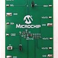
MCP4728EV
Description
BOARD EVAL 12BIT 4CH DAC MCP4728
Manufacturer
Microchip Technology
Type
D/Ar
Specifications of MCP4728EV
Number Of Dac's
4
Number Of Bits
12
Outputs And Type
1, Single Ended
Data Interface
I²C
Settling Time
6µs
Dac Type
Voltage
Voltage Supply Source
Single
Operating Temperature
-40°C ~ 125°C
Utilized Ic / Part
MCP4728
Product
Data Conversion Development Tools
Resolution
12 bit
Interface Type
I2C
Supply Voltage (max)
5.5 V
Supply Voltage (min)
2.7 V
Silicon Manufacturer
Microchip
Silicon Core Number
MCP4728
Kit Application Type
Data Converter
Application Sub Type
DAC
Kit Contents
Board
For Use With/related Products
MCP4728
Lead Free Status / RoHS Status
Lead free / RoHS Compliant
Lead Free Status / RoHS Status
Lead free / RoHS Compliant, Lead free / RoHS Compliant
Available stocks
Company
Part Number
Manufacturer
Quantity
Price
Company:

Part Number:
MCP4728EV
Manufacturer:
Microchip Technology
Quantity:
135
Company:
Part Number:
MCP4728EV
Manufacturer:
MICROCHIP
Quantity:
12 000


7.0
The MCP4728 device is a part of Microchip’s latest
DAC family with nonvolatile EEPROM memory. The
device is a general purpose resistor string DAC
intended to be used in applications where a precise
and low power DAC, with moderate bandwidth, is
required.
Since the device includes nonvolatile EEPROM
memory, the user can use this device for applications
that require the output to return to the previous set-up
value on subsequent power-ups.
Applications generally suited for the MCP4728 device
family include:
• Set Point or Offset Trimming
• Sensor Calibration
• Portable Instrumentation (Battery Powered)
• Motor Speed Control
FIGURE 7-1:
© 2010 Microchip Technology Inc.
TYPICAL APPLICATIONS
R
1
R
and R
3
Example of the MCP4728 Device Connection.
R
C
C
2
3
1
2
=
=
=
=
=
=
R
Pull-up resistors for I
5 kΩ - 10 kΩ for f
~700Ω for f
(a) Pull-up resistor to monitor RDY/BSY bit = ~ 100 kΩ
(b) Let this pin float when not used
0.1 µF, Ceramic capacitor
10 µF, Tantalum capacitor
2
RDY/BSY
R
1
LDAC
SDA
SCL
V
DD
SCL
1
2
3
4
5
=
SCL
3.4 MHz
MCP4728
2
C Serial Communications
=
100 kHz to 400 kHz
C
1
10
9
8
7
6
7.1
The SCL, SDA, and RDY/BSY pins of the MCP4728
device are open-drain configurations. These pins
require a pull-up resistor, as shown in
LDAC pin has a Schmitt trigger input configuration and
it can be driven by an external MCU I/O pin.
The pull-up resistor values (R
SDA pins depend on the operating speed (standard,
fast, and high speed) and loading capacitance of the
I
less power, but increases the signal transition time
(higher RC time constant) on the bus line. Therefore, it
can limit the bus operating speed. A lower resistor
value, on the other hand, consumes higher power, but
allows for higher operating speed. If the bus line has
higher capacitance due to long metal traces or multiple
device connections to the bus line, a smaller pull-up
resistor is needed to compensate for the long RC time
constant. The pull-up resistor is typically chosen
between 1 kΩ and 10 kΩ range for standard and fast
modes, and less than 1 kΩ for high speed mode.
2
C bus line. Higher value of pull-up resistor consumes
V
V
V
V
V
C
SS
OUT
OUT
OUT
OUT
2
D
C
B
A
Connecting to I
Pull-Up Resistors
V
DD
Analog Outputs
To MCU
2
MCP4728
C BUS Using
1
and R
DS22187E-page 51
Figure
2
) for SCL and
7-1. The
Related parts for MCP4728EV
Image
Part Number
Description
Manufacturer
Datasheet
Request
R

Part Number:
Description:
Manufacturer:
Microchip Technology Inc.
Datasheet:
Part Number:
Description:
Manufacturer:
Microchip Technology Inc.
Datasheet:
Part Number:
Description:
Manufacturer:
Microchip Technology Inc.
Datasheet:
Part Number:
Description:
Manufacturer:
Microchip Technology Inc.
Datasheet:
Part Number:
Description:
Manufacturer:
Microchip Technology Inc.
Datasheet:
Part Number:
Description:
Manufacturer:
Microchip Technology Inc.
Datasheet:
Part Number:
Description:
Manufacturer:
Microchip Technology Inc.
Datasheet:
Part Number:
Description:
Manufacturer:
Microchip Technology Inc.
Datasheet: