CDB4352 Cirrus Logic Inc, CDB4352 Datasheet
CDB4352
Specifications of CDB4352


Related parts for CDB4352


CDB4352 Summary of contents
Page 1
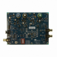
... The CS4352 is available in a 20-pin TSSOP package in both Commercial grade (-40°C to +85°C) and Automo- tive grade (-40°C to +105°C). The CDB4352 Customer Demonstration Board is also available for device evalu- ation and implementation suggestions. Please see “Ordering Information” on page 20 ...
Page 2
TABLE OF CONTENTS 1. PIN DESCRIPTIONS ............................................................................................................................. 3 2. CHARACTERISTICS AND SPECIFICATIONS ...................................................................................... 4 RECOMMENDED OPERATING CONDITIONS .................................................................................... 4 ABSOLUTE MAXIMUM RATINGS ........................................................................................................ 4 DAC ANALOG CHARACTERISTICS - COMMERCIAL (-CZZ) ............................................................. 5 DAC ANALOG CHARACTERISTICS - AUTOMOTIVE (-DZZ) .............................................................. 6 ...
Page 3
PIN DESCRIPTIONS MCLK Pin Name Pin # SDIN 1 Serial Audio Data Input (Input) - Input for two’s complement serial audio data. SCLK 2 Serial Clock (Input) - Serial clock for the serial audio interface. Left / Right Clock ...
Page 4
CHARACTERISTICS AND SPECIFICATIONS RECOMMENDED OPERATING CONDITIONS (GND = 0 V; all voltages with respect to ground.) Parameters DC Power Supply Ambient Operating Temperature (power applied) ABSOLUTE MAXIMUM RATINGS (GND = 0 V; all voltages with respect to ground.) Parameters ...
Page 5
DAC ANALOG CHARACTERISTICS - COMMERCIAL (-CZZ) Test conditions (unless otherwise specified): T and VQ capacitors as shown in Figure 2 on page ment bandwidth kHz. Parameter All Speed Modes Fs = 48, 96, and 192 kHz ...
Page 6
DAC ANALOG CHARACTERISTICS - AUTOMOTIVE (-DZZ) Test conditions (unless otherwise specified): T VBIAS+ and VQ capacitors as shown in measurement bandwidth kHz. Parameter All Speed Modes Fs = 48, 96, and 192 kHz Dynamic Range (Note ...
Page 7
COMBINED INTERPOLATION & ON-CHIP ANALOG FILTER RESPONSE (The filter characteristics have been normalized to the sample rate (Fs) and can be referenced to the desired sam- ple rate by multiplying the given characteristic by Fs. Amplitude vs. frequency plots of ...
Page 8
SWITCHING SPECIFICATIONS - SERIAL AUDIO INTERFACE Parameters MCLK Frequency MCLK Duty Cycle Input Sample Rate (Auto selection) LRCK Duty Cycle SCLK Pulse Width Low SCLK Pulse Width High SCLK Period SCLK rising to LRCK edge delay SCLK rising to LRCK ...
Page 9
DIGITAL CHARACTERISTICS Parameters High-Level Input Voltage Low-Level Input Voltage Input Leakage Current Input Capacitance Maximum MUTEC Drive Current MUTEC High-Level Output Voltage MUTEC Low-Level Output Voltage POWER AND THERMAL CHARACTERISTICS Parameters Power Supplies Power Supply Current (Note 6) power-down state, ...
Page 10
TYPICAL CONNECTION DIAGRAM +3 *Remove this supply if 10 µF optional resistor is present. The decoupling caps should remain. Digital Audio Source +1 0.1 µF Mode Configuration 10 5.1 Ω∗ *Optional 0.1 µF 0.1 ...
Page 11
APPLICATIONS 4.1 Sample Rate Range/Operational Mode Detect The device operates in one of three operational modes. The allowed sample rate range in each mode is auto-detected. The CS4352 will auto-detect the correct mode when the input sample rate (Fs), ...
Page 12
Digital Interface Format The device will accept audio samples digital interface formats, as illustrated in The desired format is selected via the DIF1 and DIF0 pins. For an illustration of the required relationship between the ...
Page 13
... DAC. If desired, all supply pins may be connected to the same supply, but a decoupling ca- pacitor should still be placed on each supply pin. Note: All decoupling capacitors should be referenced to analog ground. The CDB4352 evaluation board demonstrates the optimum layout and power supply arrangements. DS684F2 Figure 6 shows the de-emphasis curve for Fs equal to ...
Page 14
... Please see the CDB4352 data sheet for a suggested mute circuit for dual-supply systems. Alternately, the FET muting circuit from the CS4351 data sheet may be used as well. This FET circuit must be placed in series after the RC filter ...
Page 15
Initialization and Power-Down Sequence Diagram USER: Apply Power Power-Down State VQ and outputs low USER: Apply MCLK, SCLK, LRCK, and release RST VQ and outputs ramp up MCLK/LRCK Ratio Detection Analog Output is Generated DS684F2 VQ and outputs ramp ...
Page 16
DIGITAL FILTER RESPONSE PLOTS 0 −20 −40 −60 −80 −100 −120 0.4 0.5 0.6 0.7 Frequency(normalized to Fs) Figure 7. Single-Speed Stopband Rejection 0 −1 −2 −3 −4 −5 −6 −7 −8 −9 −10 0.45 0.46 0.47 0.48 0.49 ...
Page 17
Frequency(normalized to Fs) Figure 13. Double-Speed Transition Band (detail 100 120 0.2 0.3 0.4 0.5 0.6 Frequency(normalized ...
Page 18
PARAMETER DEFINITIONS Total Harmonic Distortion + Noise (THD+N) The ratio of the rms value of the signal to the rms sum of all other spectral components over the specified bandwidth (typically kHz), including distortion components. ...
Page 19
PACKAGE DIMENSIONS 20L TSSOP (4.4 mm BODY) PACKAGE DRAWING TOP VIEW INCHES DIM MIN 0.002 A2 0.03346 0.0354 b 0.00748 0.0096 D 0.252 E 0.248 0.2519 E1 0.169 0.1732 e -- ...
Page 20
... Package Pb-Free Grade Commercial 20-pin YES TSSOP Automotive - - Changes www.cirrus.com. CS4352 Temp Range Container Order # Rail CS4352-CZZ -40° to +85° C Tape & Reel CS4352-CZZR Rail CS4352-DZZ -40° to +105° C Tape & Reel CS4352-DZZR - - CDB4352 DS684F2 ...