CDB4385 Cirrus Logic Inc, CDB4385 Datasheet - Page 40
CDB4385
Manufacturer Part Number
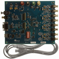
CDB4385
Description
BOARD EVAL FOR CS4385 DAC
Manufacturer
Cirrus Logic Inc
Specifications of CDB4385
Number Of Dac's
8
Number Of Bits
24
Outputs And Type
8, Differential
Sampling Rate (per Second)
192k
Data Interface
Serial
Dac Type
Voltage
Voltage Supply Source
Analog and Digital
Operating Temperature
-40°C ~ 85°C
Utilized Ic / Part
CDB4385
Description/function
Audio D/A
Operating Supply Voltage
5 V
Product
Audio Modules
For Use With/related Products
CS4385
Lead Free Status / RoHS Status
Contains lead / RoHS non-compliant
Lead Free Status / RoHS Status
Lead free / RoHS Compliant, Contains lead / RoHS non-compliant
Other names
598-1154


40
6.4.2 Direct DSD Conversion (DIR_DSD)
6.4.3 Static DSD Detect (STATIC_DSD)
6.4.4 Invalid DSD Detect (INVALID_DSD)
6.4.5 DSD Phase Modulation Mode Select (DSD_PM_MODE)
6.4.6 DSD Phase Modulation Mode Enable (DSD_PM_EN)
Function:
When set to 0 (default), DSD input data is sent to the DSD processor for filtering and volume control func-
tions.
When set to 1, DSD input data is sent directly to the switched capacitor DACs for a pure DSD conversion.
In this mode, the full-scale DSD and PCM levels will not be matched (see
performance may be reduced, the volume control is inactive, and the 50 kHz low pass filter is not available
(see
Function:
When set to 1 (default), the DSD processor checks for 28 consecutive zeroes or ones and, if detected,
sends a mute signal to the DACs. The MUTEC pins will eventually go active according to the DAMUTE
register.
When set to 0, this function is disabled.
Function:
When set to 1, the DSD processor checks for greater than 24 out of 28 bits of the same value and, if de-
tected, will attenuate the data sent to the DACs. The MUTEC pins go active according to the DAMUTE
register.
When set to 0 (default), this function is disabled.
Function:
When set to 0 (default), the 128Fs (BCKA) clock should be input to DSD_SCLK for Phase Modulation
Mode. (See
When set to 1, the 64Fs (BCKD) clock should be input to DSD_SCLK for Phase Modulation Mode.
Function:
When set to 1, DSD phase modulation input mode is enabled, and the DSD_PM_MODE bit should be set
accordingly.
When set to 0 (default), this function is disabled (DSD normal mode).
Section 1
Figure 22 on page
for filter specifications).
28)
Section
1), the dynamic range
CS4385
DS671F2
Related parts for CDB4385
Image
Part Number
Description
Manufacturer
Datasheet
Request
R

Part Number:
Description:
Development Kit
Manufacturer:
Cirrus Logic Inc
Datasheet:
Part Number:
Description:
Development Kit
Manufacturer:
Cirrus Logic Inc
Datasheet:


Part Number:
Description:
High-efficiency PFC + Fluorescent Lamp Driver Reference Design
Manufacturer:
Cirrus Logic Inc
Datasheet:
Part Number:
Description:
Development Kit
Manufacturer:
Cirrus Logic Inc
Datasheet:
Part Number:
Description:
Development Kit
Manufacturer:
Cirrus Logic Inc
Datasheet:

Part Number:
Description:
Development Kit
Manufacturer:
Cirrus Logic Inc
Datasheet:
Part Number:
Description:
Development Kit
Manufacturer:
Cirrus Logic Inc
Datasheet:
Part Number:
Description:
Development Kit
Manufacturer:
Cirrus Logic Inc
Datasheet:
Part Number:
Description:
Development Kit
Manufacturer:
Cirrus Logic Inc
Datasheet:

Part Number:
Description:
EVALUATION BOARD FOR CS8427
Manufacturer:
Cirrus Logic Inc
Datasheet:

Part Number:
Description:
BOARD EVAL FOR CS8416 RCVR
Manufacturer:
Cirrus Logic Inc
Datasheet:

Part Number:
Description:
EVALUATION BOARD FOR CS8420
Manufacturer:
Cirrus Logic Inc
Datasheet:

Part Number:
Description:
KIT DEVELOPMENT EP9315 ARM9
Manufacturer:
Cirrus Logic Inc
Datasheet:

Part Number:
Description:
KIT DEVELOPMENT EP9302 ARM9
Manufacturer:
Cirrus Logic Inc
Datasheet: