SSL2101T/DB/FBCB120V,598 NXP Semiconductors, SSL2101T/DB/FBCB120V,598 Datasheet
SSL2101T/DB/FBCB120V,598
Specifications of SSL2101T/DB/FBCB120V,598


Related parts for SSL2101T/DB/FBCB120V,598


SSL2101T/DB/FBCB120V,598 Summary of contents
Page 1
UM10341 SSL2101 12 W mains dimmable LED driver Rev. 2 — 3 February 2011 Document information Info Content Keywords SSL2101, LED driver, AC/DC conversion, dimmable, mains supply, user manual Abstract This is a user manual for the SSL2101 12 W ...
Page 2
... NXP Semiconductors Revision history Rev Date Description v.2 20110203 first issue UM10341 User manual SSL2101 12 W mains dimmable LED driver All information provided in this document is subject to legal disclaimers. Rev. 2 — 3 February 2011 UM10341 © NXP B.V. 2011. All rights reserved ...
Page 3
... NXP Semiconductors 1. Introduction WARNING Lethal voltage and fire ignition hazard The non-insulated high voltages that are present when operating this product, constitute a risk of electric shock, personal injury, death and/or ignition of fire. This product is intended for evaluation purposes only. It shall be operated in a designated test area by personnel qualified according to local requirements and labor laws to work with non-insulated mains voltages and high-voltage circuits ...
Page 4
... NXP Semiconductors 3. Connecting the board Remark: All components referred to in the text can be located on schematic diagram” diagram”. The board can be optimized for a 230 120 mains supply. In addition to the mains voltage optimization, the board is designed to work with multiple high power LEDs with a total working voltage of between 9 V and 23 V ...
Page 5
... NXP Semiconductors 4. Specifications Table 1 Table 1. Parameter AC line input voltage Output voltage (LED voltage) Output voltage protection Output current (LED current) Output voltage /load current dependency Current ripple Maximum output power (LED power) Efficiency Power Factor: 120 230 Switching frequency Dimming range ...
Page 6
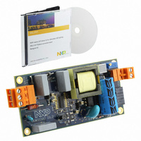
... NXP Semiconductors 5. Board photos Fig 3. Demo board (top) Fig 4. Demo board (bottom) UM10341 User manual SSL2101 12 W mains dimmable LED driver All information provided in this document is subject to legal disclaimers. Rev. 2 — 3 February 2011 UM10341 019aaa819 019aaa818 © NXP B.V. 2011. All rights reserved. ...
Page 7
... NXP Semiconductors 6. Dimmers Several triac based dimmers have been tested by NXP Semiconductors. Because different dimmers have different specifications, the dimming performance of the board may vary. board: Table 2. Manufacturer Type Opus Opus Bush-Jaeger Bush-Jaeger Bush-Jaeger Gira Everflourish Drespa Ehmann Drespa Lutron Levitron ...
Page 8
... NXP Semiconductors 7. Functional description Remark: All components referred to in the text can be located on schematic The IC controls and drives the flyback converter part, and ensures proper dimmer operation. Several high voltage switches are integrated in the IC. One of these controls the flyback input power, and is situated between the DRAIN and SOURCE pins. When the switch closes, a current stores energy in the transformer TX1 ...
Page 9
... NXP Semiconductors Two other switches are referred to as the weak bleeder (pin WBLEED) and the strong bleeder (pin SBLEED). When the voltage on these pins is below a certain value (typically 52 V) the SBLEED switch closes, providing a current path that loads the dimmer during zero voltage crossing. This resets the dimmer timer. When the voltage on either of these pins is above 52 V, and the voltage on the ISENSE pin is below − ...
Page 10
... NXP Semiconductors the LC filter within the dimmer. A serial resistor can be used for this for low power ranges (<10 W) but for higher power ranges a single series resistor is not efficient. This is because the converter supply current will cause significant voltage drop and thus dissipation through this resistor ...
Page 11
... NXP Semiconductors 8. Board optimization The following modifications must be made in order to meet different customer application requirements: Remark: All components referred to in the text can be located on schematic 8.1 Changing the output voltage and LED current When compared with other topologies, a flyback converter has the major advantage that it is suitable for driving a broader range of output voltages ...
Page 12
... NXP Semiconductors Transistor dimmers contain active circuitry that require a load charge during the time that the dimmer is open. The dimensioning of the circuit generating the internal supply voltage inside the dimmer is made critical in order to avoid excessive internal dimmer losses. This means that the remaining voltage drop over the lamp must be low enough to reach this charge. For dimmers such as the Busch-Jaeger 6519U, the minimum lamp load is specified which is equivalent to a 1.3 kΩ ...
Page 13
Fuse R3 D1 EARTH C1 RGND MAINS SBLEED R26 R25 WBLEED WBLEED V CC GND/TC BRIGHTNESS BRIGHTNESS RC2 PWMLIMIT RC R16 SBLEED R17 R15 C9 ...
Page 14
... NXP Semiconductors 10. Bill Of Materials (BOM) Table 3. Bill of materials 230 V (AC) Part Ref. Part Value or No. part no conn 3 pin K1' conn 3 pin conn 6 pin conn 2 pin K2' conn 2 pin 2 f 6.8 Ω fusistor 39 Ω resistor 39 Ω resistor 9 R3 resistor 1 kΩ resistor 470 kΩ ...
Page 15
... NXP Semiconductors Table 3. Bill of materials 230 V (AC) Part Ref. Part Value or No. part no. 4.7 μ capacitor 40 C8 capacitor 330 pF 10 μ capacitor 42 C10 capacitor 2 C11 capacitor 10 nF 680 μ inductor 330 μ inductor 100 μ inductor 47 TX1 transformer N87/3F3 48 D1 rect. bridge ...
Page 16
... NXP Semiconductors Table 4. Bill of materials 120 V (AC) Part Ref. Part No conn 3 pin 2 2 K1' conn 3 pin conn 6 pin conn 2 pin 2 5 K2' conn 2 pin fusistor 7 R1 resistor 8 R2 resistor 9 R3 resistor 10 R4 resistor 11 R5 resistor 12 R6 resistor 13 R7 resistor 14 R8 resistor 15 R9 resistor ...
Page 17
... NXP Semiconductors Table 4. Bill of materials 120 V (AC) Part Ref. Part No capacitor 42 C10 capacitor 43 C11 capacitor 44 L1 inductor 45 L2 inductor 46 L3 inductor 47 TX1 transformer 48 D1 rect bridge 49 D2 TVS diode 50 D3 diode 51 D4 Zener 52 D5 diode 53 D6 diode 54 D7 diode 55 D8 Zener ...
Page 18
... NXP Semiconductors 11. Transformer specification Figure 9 Fig 9. 11.1 Turns ratio (1 - 0.494 ± • 0.247 ± • 11.2 Electrical characteristics Table 5. Section • Nominal frequency = 100 kHz 11.3 Core and bobbin1 x Core: EFD25, 3F3/N87, air gap center 1100 μm • • Bobbin: CSH-EFD25-1S-10P 11 ...
Page 19
... NXP Semiconductors 12. Appendix A - Load curves 1.2 l out 1 0.8 0.6 0.4 6 Fig 11. 120 V (AC) load curve 1.4 l out 1.2 1 0.8 0.6 0.4 9 Fig 12. 230 V (AC) load curve UM10341 User manual All information provided in this document is subject to legal disclaimers. Rev. 2 — 3 February 2011 ...
Page 20
... NXP Semiconductors 13. Appendix B - Efficiency curves 80 η (%) Fig 13. 120 V (AC) efficiency curve 80 η (%) Fig 14. 230 V (AC) efficiency curve UM10341 User manual 10 14 800mA 700 mA 500 All information provided in this document is subject to legal disclaimers. Rev. 2 — 3 February 2011 UM10341 SSL2101 12 W mains dimmable LED driver ...
Page 21
... NXP Semiconductors 14. Appendix C - Input voltage dependency 0.68 l out (A) 0.64 0.60 0.56 0.52 100 110 120 a. 120 V (AC) Fig 15. Input voltage/output current dependency UM10341 User manual 019aaa826 0.74 l out (A) 0.72 0.7 0.68 0.66 0.64 130 140 200 V ( 220 V (AC) All information provided in this document is subject to legal disclaimers. ...
Page 22
... NXP Semiconductors 15. Appendix D - Mains conducted harmonics Table 6. Harmonic THD PF 16. References [1] AN10754 — SSL2101 and SSL2102 dimmable mains LED driver [2] SSL2101 — Data sheet [3] SMPS — IC for dimmable LED lighting UM10341 User manual Mains conducted harmonic values 230 V (AC Amplitude (%) ...
Page 23
... In no event shall NXP Semiconductors, its affiliates or their suppliers be liable to customer for any special, indirect, consequential, punitive or incidental damages (including without limitation damages for loss of business, business ...
Page 24
... NXP Semiconductors 18. Contents 1 Introduction . . . . . . . . . . . . . . . . . . . . . . . . . . . . 3 2 Safety warning . . . . . . . . . . . . . . . . . . . . . . . . . . 3 3 Connecting the board . . . . . . . . . . . . . . . . . . . . 4 4 Specifications Board photos . . . . . . . . . . . . . . . . . . . . . . . . . . . 6 6 Dimmers . . . . . . . . . . . . . . . . . . . . . . . . . . . . . . . 7 7 Functional description . . . . . . . . . . . . . . . . . . . 8 8 Board optimization . . . . . . . . . . . . . . . . . . . . . 11 8.1 Changing the output voltage and LED current . . . . . . . . . . . . . . . . . . . . . . . . . . 11 8.2 Changing the output ripple current . . . . . . . . . 11 8.3 Adapting to high power reverse phase (transistor) dimmers ...