LM3404EVAL/NOPB National Semiconductor, LM3404EVAL/NOPB Datasheet

BOARD EVALUATION LM3404

LM3404EVAL/NOPB

Manufacturer Part Number
LM3404EVAL/NOPB
Description
BOARD EVALUATION LM3404
Manufacturer
National Semiconductor
Series
PowerWise®r
Datasheets

Specifications of LM3404EVAL/NOPB

Current - Output / Channel
1A
Outputs And Type
1, Non-Isolated
Voltage - Output
4 V
Features
Dimmable
Voltage - Input
6 ~ 42 V
Utilized Ic / Part
LM3404
Silicon Manufacturer
National
Silicon Core Number
LM3404
Kit Application Type
Power Management - Voltage Regulator
Application Sub Type
Buck Regulator
Kit Contents
Board, User Guide, LM3404 Datasheet
Lead Free Status / RoHS Status
Lead free / RoHS Compliant
Other names
*LM3404EVAL
LM3404EVAL

Available stocks

Company
Part Number
Manufacturer
Quantity
Price
Part Number:
LM3404EVAL/NOPB
Manufacturer:
National Semiconductor
Quantity:
135
© 2009 National Semiconductor Corporation
LM3404/LM3404HV
Evaluation Board
Introduction
The LM3404/04HV is a buck regulator derived controlled cur-
rent source designed to drive a series string of high power,
high brightness LEDs (HBLEDs) such as the Luxeon™ K2
Emitter at forward currents of up to 1.0A. The board can ac-
cept an input voltage ranging from 6V to 42V when using the
LM3404. When using the pin-for-pin compatible LM3404HV
the upper bound of input voltage is 75V. The converter output
voltage adjusts as needed to maintain a constant current
through the LED array. The LM3404/04HV is a true step-down
regulator with an output voltage range extending from a V
(MIN)
mined by the minimum off time (typically 300 ns). It can
maintain regulated current through any number of LEDs as
long as the combined forward voltage of the array does not
exceed V
Circuit Performance LM3404
The LM3404 circuit and BOM have been designed to provide
a constant forward current of 1.0A to a single LED with a for-
ward voltage of approximately 3.7V (Typical of white, blue,
and green LEDs using InGaN technology) from an input of
24V ±10%. Over the input voltage range of 6V to 42V the av-
erage LED current, I
will not exceed 400 mA
kHz ± 10%.
Circuit Performance LM3404HV
The LM3404HV circuit and BOM have been designed to pro-
vide a constant forward current of 1.0A to a single LED with
a forward voltage of approximately 3.7V from an input of 48V
±10%. Over the input voltage range of 6V to 75V the average
LED current, I
exceed 400 mA
10%.
Connecting to LED Array
The LM3404/04HV Evaluation Board includes a female 6-pin
SIP, J1, connector as well as two standard 94mil turret con-
nectors for the cathode and anode connections of the LED
array. Figure 1 shows the pinout of J1. Solid 18 or 20 gauge
wire with about 1 cm of insulation stripped away makes a
convenient, solderless connection to J1.
of 200 mV (the reference voltage) to a V
O(MAX).
F
, is 1.0A ±10%, the ripple current, Δi
P-P
.
, and the switching frequency is 200 kHz ±
F
, is 1.0A ±10%, the ripple current, Δi
P-P
, and the switching frequency is 450
202159
O(MAX)
F
, will not
deter-
F
O
,
National Semiconductor
Application Note 1545
Chris Richardson
August 14, 2009
Setting the LED Current
The default forward current I
1.0A, typical of many 3W LEDs. To adjust this value the cur-
rent setting resistor R
following equation:
This resistor should be rated to handle the power dissipation
of the LED current. For example, the closest 5% tolerance
resistor to set an LED current of 1.0A is 0.22 Ω. In steady state
this resistor will dissipate (1.0 x 0.22) = 220 mW, indicating
that a resistor with a 1/4W power rating is appropriate.
PWM Dimming
The DIM1 terminal on the PCB provides an input for a pulse
width modulation signal for dimming of the LED array. In order
to fully enable and disable the LM3404/04HV the PWM signal
should have a maximum logic low level of 0.8V and a mini-
mum logic high level of 2.2V. The maximum PWM dimming
frequency, minimum PWM duty cycle and maximum duty cy-
cle are illustrated in Figure 2. PWM frequency should be at
least one order of magnitude below the LM3404/04HV switch-
ing frequency. The interval t
logic high at the DIM pin to the onset of the output current.
The quantities t
output current to slew up to steady state and slew down to
zero, respectively. Typical response times for the standard
LM3404 and LM3404HV demo boards circuits are shown in
the Typical Performance Characteristics section.
SU
and t
SNS
t
SD
SNS
FIGURE 1.
can be changed according to the
represent the time needed for the
= 220 ns
LED
D
represents the delay from a
delivered to the LED array is
20215901
www.national.com

Related parts for LM3404EVAL/NOPB

LM3404EVAL/NOPB Summary of contents

Page 1

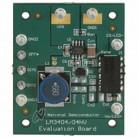
... LED array. Figure 1 shows the pinout of J1. Solid gauge wire with about insulation stripped away makes a convenient, solderless connection to J1. © 2009 National Semiconductor Corporation National Semiconductor Application Note 1545 Chris Richardson August 14, 2009 ...

Page 2

The logic of DIM1 is direct, hence the LM3404/04HV will de- liver regulated output current when the voltage at DIM1 is high, and the current output is disabled when the voltage at DIM1 is low. Connecting a constant logic low ...

Page 3

ID Part Number U1 LM3404 L1 SLF10145T- 330M1R6 D1 CMSH2-60M Cf VJ0805Y104KXXAT Cb VJ0805Y103KXXAT Cin C3225X7R1H335M Rsns ERJ8BQFR22V Ron CRCW08056812F Rz CRCW08050R00F DIM1, DIM2, 160-1512 OFF* GND1, GND2, 160-1026 GND3, VIN, Vo/ LED+, CS/LED- J1 535676-5 FIGURE 3. Standard Schematic ...

Page 4

ID Part Number U1 LM3404HV L1 SLF12555T- 680M1R3 D1 CMSH2-100 Cf VJ0805Y104KXXAT Cb VJ0805Y103KXXAT Cin C4532X7R2A225M Co1 C3216X7R2A105M Rsns ERJ8BQFR22V Ron CRCW08051743F Rz CRCW08050R00F DIM1, DIM2, OFF* 160-1512 GND1, GND2, 160-1026 GND3, VIN, Vo/ LED+, CS/LED- J1 535676-5 www.national.com TABLE ...

Page 5

Typical Performance Characteristics Efficiency for Table 25° 1. for Table 25°C A DIM Pin Enable for Table 1 Efficiency for Table 20215908 ...

Page 6

Switching Waveforms for Table 1 DIM Pin Enable for Table 2 Switching Waveforms for Table 2 www.national.com Output Ripple Current for Table 1 20215914 DIM Pin Disable for Table 2 20215916 Output Ripple Current for Table 2 20215918 6 20215915 ...

Page 7

Layout Top Layer and Top Overlay 7 20215906 www.national.com ...

Page 8

Bottom Layer and Bottom Overlay 8 20215907 ...

Page 9

Notes 9 www.national.com ...

Page 10

... For more National Semiconductor product information and proven design tools, visit the following Web sites at: Products Amplifiers www.national.com/amplifiers Audio www.national.com/audio Clock and Timing www.national.com/timing Data Converters www.national.com/adc Interface www.national.com/interface LVDS www.national.com/lvds Power Management www.national.com/power Switching Regulators www.national.com/switchers LDOs www.national.com/ldo LED Lighting www ...

Related keywords