RDK-193 Power Integrations, RDK-193 Datasheet
RDK-193
Specifications of RDK-193
Available stocks


Related parts for RDK-193


RDK-193 Summary of contents
Page 1
... No damage during brown-out or brown-in conditions Meets IEC 61000-4-5 ringwave, IEC 61000-3-2 Class C harmonics and EN55015 B conducted EMI 5245 Hellyer Avenue, San Jose, CA 95138 USA. Tel: +1 408 414 9200 Fax: +1 408 414 9201 LED Driver Using TYP ® -PH LNK403EG TYP Power Integrations www.powerint.com , 0.33 A Output ...
Page 2
... The products and applications illustrated herein (including transformer construction and circuits external to the products) may be covered by one or more U.S. and foreign patents, or potentially by pending U.S. and foreign patent applications assigned to Power Integrations. A complete list of Power Integrations' patents may be found at www.powerint.com. Power Integrations grants its customers a license under certain patent rights as set forth at < ...
Page 3
... Input Phase vs. Output Current .........................................................................30 13.2 Output Voltage and Input Current Waveforms During Dimming ........................31 13.2 115 VAC / 60 Hz ................................................................................31 IN 13.2 230 VAC / 50 Hz ................................................................................ Line Surge.............................................................................................................33 15 Conducted EMI .....................................................................................................34 16 Production Distribution Data..................................................................................36 Page Power Integrations Tel: +1 408 414 9200 Fax: +1 408 414 9201 www.powerint.com ...
Page 4
... Important Note: Although this board is designed to satisfy safety isolation requirements, the engineering prototype has not been agency approved. Therefore, all testing should be performed using an isolation transformer to provide the AC input to the prototype board. Power Integrations, Inc. Tel: +1 408 414 9200 Fax: +1 408 414 9201 www.powerint.com ...
Page 5
... The document describes a high power-factor corrected dimmable LED driver designed to drive 0.33 A from an input voltage range of 90 VAC to 265 VAC. The LED driver utilizes the LNK403EG from Power Integrations. LinkSwitch-PH ICs allow the implementation of cost effective and low component count LED drivers which both meet power factor and harmonics limits but also offer enhanced end user experience ...
Page 6
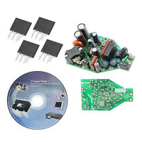
... Figure 1 – Populated Circuit Board Photograph (Top View). PCB Outline Designed to Fit Inside PAR20 Enclosure. Figure 2 – Populated Circuit Board Photograph (Bottom View). Power Integrations, Inc. Tel: +1 408 414 9200 Fax: +1 408 414 9201 www.powerint.com Page ...
Page 7
... EN 61000-3-2 Class AMB Tel: +1 408 414 9200 Fax: +1 408 414 9201 Units Comment VAC 2 Wire – 115 VAC, 25°C OUT Measured OUT kV IEC 61000-4-5 , 200 A Measured OUT(TYP) OUT(TYP) and 115/230 VAC o C Free convection, sea level Power Integrations www.powerint.com ...
Page 8
... Schematic Power Integrations, Inc. Tel: +1 408 414 9200 Fax: +1 408 414 9201 www.powerint.com Figure 3 – Schematic. Page ...
Page 9
... R16 for the first 2 115 VAC (1 230 VAC) of the TRIAC conduction. After approximately 2.4 ms, Q3 turns on and shorts R16. This keeps the power dissipation on R16 low. Resistor R12, R13, R20 and C13 provide a 2.4 ms Page Power Integrations Tel: +1 408 414 9200 Fax: +1 408 414 9201 www.powerint.com ...
Page 10
... TRIAC conducts. Transistor Q1 discharges C13 when the TRIAC is not conducting. Zener VR2 clamps the gate voltage Capacitor C9 and R14 keep the TRIAC current above the holding threshold to prevent multiple firings. Power Integrations, Inc. Tel: +1 408 414 9200 Fax: +1 408 414 9201 www.powerint.com Page ...
Page 11
... PCB Layout Figure 4 – Printed Circuit Layout (Designed to Fit Inside PAR20 Lamp Form Factor). Page Power Integrations Tel: +1 408 414 9200 Fax: +1 408 414 9201 www.powerint.com ...
Page 12
... W, Thick Film, 1206 35 1 R14 1 k, 5 Metal Oxide 36 1 R15 143 k, 1%, 1/8 W, Thick Film, 0805 Power Integrations, Inc. Tel: +1 408 414 9200 Fax: +1 408 414 9201 www.powerint.com Mfg Part Number Mfg DF06S-E3/45 Vishay ECQ-U2A223ML Panasonic ECQ-E4104KF ...
Page 13
... CFR-50JB-270R ERJ-6ENF15R0V ERJ-6ENF4992V ERJ-6GEYJ245V ERJ-6GEYJ103V ERZ-V10D431 SNX-R1537 Santronics USA 5000 5001 LNK406EG Power Integrations 1.5KE200A-E3/54 ZMM5245B-7 ZMM5259B-7 Power Integrations Tel: +1 408 414 9200 Fax: +1 408 414 9201 www.powerint.com Yageo Panasonic Panasonic Panasonic Panasonic Panasonic Keystone Keystone Vishay Diodes Inc Diodes Inc ...
Page 14
... Magnet Wire: #36 AWG [5] Magnet Wire: #28 AWG T.I.W. [6] Tape: 3M 1298 Polyester Film wide. [7] Mounting clip, CLI/P-RM6, and varnish. Power Integrations, Inc. Tel: +1 408 414 9200 Fax: +1 408 414 9201 www.powerint.com Figure 5 – Transformer Electrical Diagram. Description 3000 VAC 2.45 mH ± 10% 750 kHz (Min.) 35 ...
Page 15
... Apply three layers of tape [6] for insulation. Final Cut FL1, FL2, FL3 wire length to 0.75”. Grind core. Assemble core and varnish using Assembly item [7]. Page Figure 6 – Transformer Build Diagram. Tel: +1 408 414 9200 Fax: +1 408 414 9201 3L Tape 1L Tape 1L Tape 1L Tape Power Integrations www.powerint.com ...
Page 16
... Expected IO (average) KP_VACMAX TON_MIN ENTER TRANSFORMER CORE/CONSTRUCTION VARIABLES Core Type RM6 Bobbin AE 0.3600 Power Integrations, Inc. Tel: +1 408 414 9200 Fax: +1 408 414 9201 www.powerint.com LinkSwitch-PH_042910: Flyback Transformer INFO OUTPUT UNIT Design Spreadsheet !!! Info. When configured for dimming, best output current line regulation is achieved over a single input YES voltage range ...
Page 17
... AWG value) 0.32 mm Secondary Minimum Bare Conductor Diameter Secondary Maximum Outside Diameter for Triple 0.29 mm Insulated Wire Estimated Maximum Drain Voltage assuming maximum LED string voltage (Includes Effect of Leakage 628 V Inductance) Tel: +1 408 414 9200 Fax: +1 408 414 9201 Power Integrations www.powerint.com ...
Page 18
... IO2 RFB1 (new) RFB2(new) Note: Actual R = 142 k due to lower bias voltage. Measured PF at 230 VAC was 0.9. FB Power Integrations, Inc. Tel: +1 408 414 9200 Fax: +1 408 414 9201 www.powerint.com Output Rectifier Maximum Peak Inverse Voltage (calculated at VOVP, excludes leakage inductance 90 ...
Page 19
... Tel: +1 408 414 9200 Fax: +1 408 414 9201 P Efficiency OUT PF (W) (%) 6.20 81 6.62 82 7.22 82 0.97 7. Efficiency OUT PF (W) (%) 8.98 83 9.24 83 9.50 83 9.76 83 0.9 10.00 83 10. Efficiency OUT PF (W) (%) 5.36 82 5.70 82 6.19 83 0.96 6. Efficiency OUT PF (W) (%) 7.70 83 7.91 83 8.14 83 8.36 83 0.88 8.57 82 8.84 82 Power Integrations www.powerint.com ...
Page 20
... 100 125 Figure 7 – Efficiency vs. Input Voltage, Room Temperature. Power Integrations, Inc. Tel: +1 408 414 9200 Fax: +1 408 414 9201 www.powerint.com OUT OUT (W) (V) (mA) 8.76 24.07 290 9.26 24.17 309 24.35 337 24.49 359 P V ...
Page 21
... Table 1 – Feedback Resistor Value to Center Output Current at Different Nominal Line Voltages. Page Output Voltage (VDC) Line Voltage Value of R15 (VAC) (kΩ) 100 133 115 143 230 182 Tel: +1 408 414 9200 Fax: +1 408 414 9201 Power Integrations www.powerint.com 25 ...
Page 22
... Figure 9 – Low Line Regulation, Room Temperature, Full Load. Power Integrations, Inc. Tel: +1 408 414 9200 Fax: +1 408 414 9201 www.powerint.com 100 105 110 115 Input Voltage (VAC) 120 125 130 135 Page ...
Page 23
... Figure 10 – High Line Regulation, Room Temperature, Full Load. Page 210 220 230 240 Input Voltage (VAC) Tel: +1 408 414 9200 Fax: +1 408 414 9201 250 260 270 Power Integrations www.powerint.com ...
Page 24
... V = 115 VAC IN Figure 11 – Top Side. 10 230 VAC IN Figure 13 – Top Side. Power Integrations, Inc. Tel: +1 408 414 9200 Fax: +1 408 414 9201 www.powerint.com Figure 12 – Bottom Side. Figure 14 – Bottom Side. Page ...
Page 25
... Harmonic Data The design passes Class C requirement Figure 15 – 115 VAC Harmonic, Room Temperature, Full Load. Page Class C Limit RD-193 Harmonic Data at 115 VAC Harmonic Power Integrations Tel: +1 408 414 9200 Fax: +1 408 414 9201 www.powerint.com ...
Page 26
... Figure 16 – 230 VAC Harmonic, Room Temperature, Full Load. THD (%) 21.00 THD (%) 27.80 Power Integrations, Inc. Tel: +1 408 414 9200 Fax: +1 408 414 9201 www.powerint.com Class C limit RD-193 Harmonic Data at 230 VAC Harmonic V =115 VAC IN Limit (%) Margin (%) 33 12 230 VAC IN Limit (%) ...
Page 27
... Lower: V DRAIN Page Figure 18 – 265 VAC, Full Load. Upper 0 div. IN Lower 500 V / div div. IN Figure 20 – 265 VAC, Full Load. Upper 0 div. DRAIN , 200 V / div., 5 s / div. Lower: V DRAIN Power Integrations Tel: +1 408 414 9200 Fax: +1 408 414 9201 www.powerint.com ...
Page 28
... Drain Voltage and Current Start-up Profile ` Figure 23 – 90 VAC, Full Load. Upper 0 div. DRAIN Lower div. OUTPUT, Power Integrations, Inc. Tel: +1 408 414 9200 Fax: +1 408 414 9201 www.powerint.com Figure 22 – 265 VAC, Full Load. Upper 0 div. RIPPLE Lower div. ...
Page 29
... Figure 27 – Output Voltage: 115 VAC div., 500 ms / div. OUT Page Figure 26 – 265 VAC, Full Load. Upper div. OUTPUT Lower: V 200 V, 200 ms / div. DRAIN, Figure 28 – Output Voltage: 230 VAC div., 500 ms / div. OUT Power Integrations Tel: +1 408 414 9200 Fax: +1 408 414 9201 www.powerint.com ...
Page 30
... VAC 0.45 230 VAC 0.4 0.35 0.3 0.25 0.2 0.15 0.1 0. Figure 29 – Input Phase vs. Output Current. Power Integrations, Inc. Tel: +1 408 414 9200 Fax: +1 408 414 9201 www.powerint.com 115 VAC 230 VAC I (mA) Phase Angle OUT 310 160 150 ...
Page 31
... V / div. OUT Lower 0 div div. IN Page Figure 31 – 115 VAC, 60° Phase. Upper div. OUT Lower 0 div div. IN Figure 33 – 115 VAC, 8° Phase. Upper div. OUT Lower 0 div div. IN Power Integrations Tel: +1 408 414 9200 Fax: +1 408 414 9201 www.powerint.com ...
Page 32
... Lower 0 div div. IN Figure 36 – 230 VAC, 34° Phase. Upper div. OUT Lower 0 div div. IN Power Integrations, Inc. Tel: +1 408 414 9200 Fax: +1 408 414 9201 www.powerint.com Figure 35 – 230 VAC, 49° Phase. Upper div. OUT Lower 0 div div. IN Figure 37 – 230 VAC, 12° Phase. ...
Page 33
... Unit passes under all test conditions. Page Injection Injection Phase Location (° Tel: +1 408 414 9200 Fax: +1 408 414 9201 Test Result (Pass/Fail) Pass Pass Pass Pass Pass Pass Power Integrations www.powerint.com ...
Page 34
... Average 1 Quasi Peak 2 Average 1 Quasi Peak Figure 38 – Conducted EMI, Maximum Steady State Load, 115 VAC, 60 Hz, and EN55015 B Limits. Power Integrations, Inc. Tel: +1 408 414 9200 Fax: +1 408 414 9201 www.powerint.com RBW 9 kHz MT 500 ms Att 10 dB AUTO 100 kHz 1 MHz ...
Page 35
... L1 gnd 4.37559352882 MHz 40.83 N gnd 4.55326017222 MHz 46.83 N gnd Tel: +1 408 414 9200 Fax: +1 408 414 9201 10 MHz SGL TDF 6DB 30 MHz DELTA LIMIT dB -16.60 -14.95 -19.42 -17.11 -15.94 -19.69 -14.13 -15.54 -15.25 -14.50 -12.44 -13.08 -5.16 -9.16 Power Integrations www.powerint.com ...
Page 36
... Histogram of Average Output Current 0.30 0.31 Figure 40 – Production Variation of I Power Integrations, Inc. Tel: +1 408 414 9200 Fax: +1 408 414 9201 www.powerint.com Normal Vin = 115 VAC 0.32 0.33 0.34 Iout (A) OUT Mean 0.3358 StDev 0.003328 ...
Page 37
... Revision History Date Author 09-Jun-10 DK Page Revision Description & changes 1.0 Initial Release Tel: +1 408 414 9200 Fax: +1 408 414 9201 Reviewed Apps and Mktg Power Integrations www.powerint.com ...
Page 38
... KBE 7 China MANK 8 China SB Electric 9 China EBAHuang 10 China Myongbo 11 China TCL 12 Italy RTS34DLI Power Integrations, Inc. Tel: +1 408 414 9200 Fax: +1 408 414 9201 www.powerint.com Max Current (mA) WS-5005 325 OB4911 324 GLR11-F38875 288 XH004186 310 (mA) Y-25088A 440 Y-25082A 439 D-2160B 442 ...
Page 39
... Hz Figure 41 – 2 kHz – 22 kHz. +80 +70 +60 +50 +40 +30 +20 +10 +0 -10 -20 - 10k 12k 14k 16k Hz Figure 42 – 2 kHz – 22 kHz. Tel: +1 408 414 9200 Fax: +1 408 414 9201 18k 20k 22k 18k 20k 22k Power Integrations www.powerint.com ...
Page 40
... V = 230 VAC, Full Phase IN +80 +70 +60 +50 + +20 A +10 18.2 230 VAC, Half Phase Power Integrations, Inc. Tel: +1 408 414 9200 Fax: +1 408 414 9201 www.powerint.com +0 -10 -20 - 10k 12k 14k 16k Hz Figure 43 – 2 kHz – 22 kHz. +80 +70 +60 +50 +40 +30 +20 +10 ...
Page 41
... Power Integrations reserves the right to make changes to its products at any time to improve reliability or manufacturability. Power Integrations does not assume any liability arising from the use of any device or circuit described herein. POWER INTEGRATIONS MAKES NO WARRANTY HEREIN AND SPECIFICALLY DISCLAIMS ALL WARRANTIES INCLUDING, WITHOUT LIMITATION, THE IMPLIED WARRANTIES OF MERCHANTABILITY, FITNESS FOR A PARTICULAR PURPOSE, AND NON-INFRINGEMENT OF THIRD PARTY RIGHTS ...