SOT23-5EV-VREG Microchip Technology, SOT23-5EV-VREG Datasheet
SOT23-5EV-VREG
Specifications of SOT23-5EV-VREG


Related parts for SOT23-5EV-VREG


SOT23-5EV-VREG Summary of contents
Page 1
... Microchip Technology Inc. SOT23-5 Voltage Regulator Evaluation Board User’s Guide DS51811A ...
Page 2
... PowerInfo, PowerMate, PowerTool, REAL ICE, rfLAB, Select Mode, Total Endurance, TSHARC, WiperLock and ZENA are trademarks of Microchip Technology Incorporated in the U.S.A. and other countries. SQTP is a service mark of Microchip Technology Incorporated in the U.S.A. All other trademarks mentioned herein are property of their respective companies. ...
Page 3
... Customer Support ................................................................................................. 3 Document Revision History ................................................................................... 3 Chapter 1. Product Overview 1.1 Introduction ..................................................................................................... 5 1.2 What is the SOT23-5 Voltage Regulator Evaluation Board? .......................... 5 1.3 What the SOT23-5 Voltage Regulator Evaluation Board kit includes? .......... 7 Chapter 2. Installation and Operation 2.1 ntroduction ...................................................................................................... 9 2.2 Features ......................................................................................................... 9 2.3 Getting Started ............................................................................................. 10 Appendix A. Schematic and Layouts A ...
Page 4
... SOT23-5 Voltage Regulator Evaluation Board User’s Guide NOTES: DS51811A-page iv © 2009 Microchip Technology Inc. ...
Page 5
... Customer Support • Document Revision History DOCUMENT LAYOUT This document describes how to use the SOT23-5 Voltage Regulator Evaluation Board as a development tool to emulate and debug firmware on a target board. The manual layout is as follows: • Chapter 1. “Product Overview” – Important information about the SOT23-5 Voltage Regulator Evaluation Board. • ...
Page 6
... SOT23-5 Voltage Regulator Evaluation Board User’s Guide CONVENTIONS USED IN THIS GUIDE This manual uses the following documentation conventions: DOCUMENTATION CONVENTIONS Description Arial font: Italic characters Initial caps Quotes Underlined, italic text with right angle bracket Bold characters N‘Rnnnn Text in angle brackets < > ...
Page 7
... RECOMMENDED READING This user's guide describes how to use SOT23-5 Voltage Regulator Evaluation Board. Other useful documents are listed below. The following Microchip documents are available and recommended as supplemental reference resources. MCP1801 Data Sheet - “150 mA, High PSRR, Low Quiescent Current LDO”, DS22051 MCP1802 Data Sheet - “ ...
Page 8
... SOT23-5 Voltage Regulator Evaluation Board User’s Guide NOTES: DS51811A-page 4 © 2009 Microchip Technology Inc. ...
Page 9
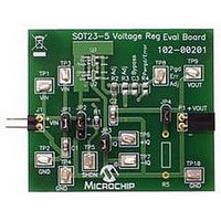
... By soldering the desired device to the evaluation board, the user can easily validate several parameters of the device. 1.2.1 Funtional Blocks The SOT23-5 Voltage Regulator Evaluation Board can be broken up into six functional blocks. These blocks are: • Input Capacitance • Shutdown Control • ...
Page 10
... SOT23-5 Voltage Regulator Evaluation Board User’s Guide 1.2.2 Input Capacitance Jumper JP1 connects the input capacitance to the circuit. The input capacitor is disconnected when performing Power Supply Ripple Rejection tests. By default populated with a 1 µF, 50V, XR7 ceramic capacitor. 1.2.3 Shutdown Control Jumper JP2 allows the user to select the Shutdown (SHDN) pin voltage level ...
Page 11
... WHAT THE SOT23-5 VOLTAGE REGULATOR EVALUATION BOARD KIT INCLUDES? This SOT23-5 Voltage Regulator Evaluation Board kit includes: • One SOT23-5 Voltage Regulator Evaluation Board -102-00201 • Important Information "Read First" © 2009 Microchip Technology Inc. DS51811A-page 7 ...
Page 12
... SOT23-5 Voltage Regulator Evaluation Board User’s Guide NOTES: DS51811A-page 8 © 2009 Microchip Technology Inc. ...
Page 13
... The jumpers may also be used to select pull-up and pull- down voltage levels. The SOT23-5 Voltage Regulator Evaluation Board kit comes with ceramic input and output capacitor soldered to the board. A 10K resistor in series with the SHDN pin is also populated on the board. The PWRGD/ADJ pin has a 69.8 kΩ resistor soldered to the board ...
Page 14
... The SOT23-5 Voltage Regulator Evaluation Board is fully assembled and tested. All that is required for operating is a user supplied voltage regulator and a supply voltage source. Some of the tests that may be completed using the SOT23-5 Voltage Regulator Evaluation Board shall now be described. 2.3.1 ...
Page 15
... Power Supply Rejection Ratio (PSRR) Power Supply Rejection Ratio tests are performed by removing the input capacitor jumper, JP1, and connecting an appropriate PSRR analyzer to the SOT23-5 Voltage Regulator Evaluation Board. The PSRR analyzer may then sweep the input voltage frequencies and record the corresponding output voltages. ...
Page 16
... SOT23-5 Voltage Regulator Evaluation Board User’s Guide NOTES: DS51811A-page 12 © 2009 Microchip Technology Inc. ...
Page 17
... EVALUATION BOARD USER’S GUIDE Appendix A. Schematic and Layouts A.1 INTRODUCTION This appendix contains the following schematics and layouts for the SOT23-5 Voltage Regulator Evaluation Board: • Board - Schematic • Board - Top Silk and Pads • Board - Top Copper • Board - Bottom Copper © ...
Page 18
... SOT23-5 Voltage Regulator Evaluation Board User’s Guide A.2 BOARD - SCHEMATIC DS51811A-page 14 © 2009 Microchip Technology Inc. ...
Page 19
... A.3 BOARD - TOP SILK AND PADS © 2009 Microchip Technology Inc. DS51811A-page 15 ...
Page 20
... SOT23-5 Voltage Regulator Evaluation Board User’s Guide A.4 BOARD - TOP COPPER DS51811A-page 16 © 2009 Microchip Technology Inc. ...
Page 21
... A.5 BOARD - BOTTOM COPPER © 2009 Microchip Technology Inc. DS51811A-page 17 ...
Page 22
... SOT23-5 Voltage Regulator Evaluation Board User’s Guide NOTES: DS51811A-page 18 © 2009 Microchip Technology Inc. ...
Page 23
... On Each Bumpon Hemisphere, 0.44 x 0.20, Black Corner socket, 0.100 centers, 0.025 sq pins, 0.070 pcb to pin center height 1 PCB RoHS Compliant Bare PCB, SOT23-5 Voltage Regulator Evaluation Board(250 boards, 4wk delivery 10K Res, Smt 0805, 1%, 1/ 69.8K Res, Smt 0805, 1%, 1/8W 3 ...
Page 24
... Fax: 886-3-6578-370 Taiwan - Kaohsiung Tel: 886-7-536-4818 Fax: 886-7-536-4803 Taiwan - Taipei Tel: 886-2-2500-6610 Fax: 886-2-2508-0102 Thailand - Bangkok Tel: 66-2-694-1351 Fax: 66-2-694-1350 © 2009 Microchip Technology Inc. EUROPE Austria - Wels Tel: 43-7242-2244-39 Fax: 43-7242-2244-393 Denmark - Copenhagen Tel: 45-4450-2828 Fax: 45-4485-2829 France - Paris Tel: 33-1-69-53-63-20 ...