EK61 Cirrus Logic Inc, EK61 Datasheet - Page 2
EK61
Manufacturer Part Number
EK61
Description
KIT EVALUATION PA78/PA79
Manufacturer
Cirrus Logic Inc
Series
Apex Precision Power™r
Specifications of EK61
Channels Per Ic
1 - Single, 2 - Dual
Amplifier Type
Power
Output Type
Single-Ended
Board Type
Bare (Unpopulated)
Utilized Ic / Part
PA78DK, PA79DK
Product
Amplifier Modules
Description/function
Audio Amplifiers
For Use With/related Products
PA78DK, PA79DK
Lead Free Status / RoHS Status
Contains lead / RoHS non-compliant
Operating Temperature
-
Current - Output / Channel
-
Voltage - Supply, Single/dual (±)
-
-3db Bandwidth
-
Slew Rate
-
Current - Supply (main Ic)
-
Lead Free Status / RoHS Status
Lead free / RoHS Compliant, Contains lead / RoHS non-compliant
Other names
598-1398
EK61
EK61


EK61
BEFORE YOU GET STARTED
• All Apex Precision Power
• Review the Apex Precision Power
• Always provide the appropriate heat sinking. Power dissipation must be considered to ensure maximum junction
• Always use adequate power supply bypass capacitors, Apex Precision Power
• Do not change connections while the circuit is powered
• In case -Vs is disconnected before +Vs, a diode between -Vs and ground is recommended to avoid damage.
• Initially set all power supplies to the minimum operating levels allowed in the product datasheet.
• Check for oscillations up to and above the unity gain bandwidth of the amplifier.
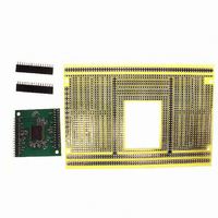
ASSEMBLY
The PA78DK & PA79DK are surface mount device and should be assembled to the EVAL61 substrate using surface
mount processes. Solder paste may be dispensed or screen-printed on the DUT pads. The heat slug on the back
of the PA78DK & PA79DK provides maximum heat dissipation capabilities when soldered to the foil footprint area.
The PA78DK & PA79DK should be reflowed to the substrate using a solder reflow furnace. If this is not available, a
heat plate capable of solder reflow temperatures may be used.
In accordance with the PA78DK and PA79DK datasheets, the package tab must be connected to a stable voltage
reference in order to achieve high slew rates. Jumpers J1 and J2 allow convenient connection of the tab to -Vs or
GND, respectively. Connect only one jumper to avoid a short circuit of the power supply.
Once the amplifier is mounted on the top of the substrate, the heat sink fan or selected heat sink can then be
mounted to the back of the substrate. A heat sink is not supplied with the kit, but several options are available
through AAVID Thermal Product, Inc. High thermal conductive thermal grease should be used when mounting the
heat sink fan or heat sink to the evaluation board.
Review Figure 3 on next page for other possible assembly methods to construct this evaluation kit.
NOTE: All grounds must be tied together on the EVAL36 board.
2
temperature (T
amp of output current.
J
) is not exceeded.
TM
amplifiers should be handled using ESD precaution.
TM
product datasheet and operating conditions.
Figure 2 - Schematic
P r o d u c t I n n o v a t i o n F r o m
TM
recommends at least 10µF per
EK61U
Related parts for EK61
Image
Part Number
Description
Manufacturer
Datasheet
Request
R

Part Number:
Description:
Development Kit
Manufacturer:
Cirrus Logic Inc
Datasheet:
Part Number:
Description:
Development Kit
Manufacturer:
Cirrus Logic Inc
Datasheet:


Part Number:
Description:
High-efficiency PFC + Fluorescent Lamp Driver Reference Design
Manufacturer:
Cirrus Logic Inc
Datasheet:
Part Number:
Description:
Development Kit
Manufacturer:
Cirrus Logic Inc
Datasheet:
Part Number:
Description:
Development Kit
Manufacturer:
Cirrus Logic Inc
Datasheet:

Part Number:
Description:
Development Kit
Manufacturer:
Cirrus Logic Inc
Datasheet:
Part Number:
Description:
Development Kit
Manufacturer:
Cirrus Logic Inc
Datasheet:
Part Number:
Description:
Development Kit
Manufacturer:
Cirrus Logic Inc
Datasheet:
Part Number:
Description:
Development Kit
Manufacturer:
Cirrus Logic Inc
Datasheet:

Part Number:
Description:
EVALUATION BOARD FOR CS8427
Manufacturer:
Cirrus Logic Inc
Datasheet:

Part Number:
Description:
BOARD EVAL FOR CS8416 RCVR
Manufacturer:
Cirrus Logic Inc
Datasheet:

Part Number:
Description:
EVALUATION BOARD FOR CS8420
Manufacturer:
Cirrus Logic Inc
Datasheet:

Part Number:
Description:
KIT DEVELOPMENT EP9315 ARM9
Manufacturer:
Cirrus Logic Inc
Datasheet:

Part Number:
Description:
KIT DEVELOPMENT EP9302 ARM9
Manufacturer:
Cirrus Logic Inc
Datasheet: