MCP6S22DM-PICTL Microchip Technology, MCP6S22DM-PICTL Datasheet - Page 16
MCP6S22DM-PICTL
Manufacturer Part Number
MCP6S22DM-PICTL
Description
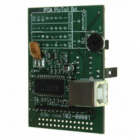
BOARD DEMO FOR MCP6S22
Manufacturer
Microchip Technology
Series
PICtail™r
Specifications of MCP6S22DM-PICTL
Channels Per Ic
2 - Dual
Amplifier Type
Programmable Gain
Output Type
Single-Ended, Rail-to-Rail
Slew Rate
22 V/µs
-3db Bandwidth
12MHz
Current - Output / Channel
30mA
Operating Temperature
-40°C ~ 85°C
Current - Supply (main Ic)
1mA
Voltage - Supply, Single/dual (±)
2.5 V ~ 5.5 V
Board Type
Fully Populated
Utilized Ic / Part
MCP6S22
Lead Free Status / RoHS Status
Contains lead / RoHS non-compliant
Available stocks
Company
Part Number
Manufacturer
Quantity
Price

Part Number:
MCP6S22DM-PICTL
Manufacturer:
MICROCHIP/微芯
Quantity:
20 000


MCP6S22 PGA PICtail™ Demo Board User’s Guide
DS51481A-page 12
When the MCP6S22 PGA PICtail Demo Board is connected to the PICkit 1 Flash
Starter Kit, the gain and channel configuration DIP switch (S
button switch (S
on-board USB PICmicro microcontroller (PIC16C745) are configured as
high-impedance inputs. This prevents a potential serial bus conflict if the
user-developed firmware for the MCP6S22 PGA PICtail Demo Board and the PICmicro
microcontroller on the PGA demo board try to access the PGA at the same time.
2.4.7
Soldering pads are provided on this MCP6S22 Demo Board for SMA connectors and
prototype circuit development. These pads are different from the traditional
through-hole prototype area. In order to measure optimum PGA performance, it is
essential that the analog circuit have a solid ground plane. Therefore, this demo board
is developed on a four-layer board with a minimum number of through-holes through
the analog ground plane. Because of this, the pins may need to be bent accordingly for
soldering purposes.
Regulated 4.1V supply voltage (V
CH1) and PGA output (V
V
The illustration below shows how the SMA connectors are slid onto the board at test
points CH0, CH1 and V
of the square lugs go underneath the board on the unmasked ground fill (bottom metal).
Solder the lugs and center conductor to the board.
FIGURE 2-2:
REG
is heavily loaded, the 4.1V may be reduced.
Using the Prototype Area
1
) cannot be used to configure the PGA. The serial I/O lines from the
SMA Connectors.
OUT
OUT_PGA
. The round center conductor goes over the test pad and two
REG
) signals are also available on the prototype area. If
SMA Connector and Board (side view)
), ground (GND), PGA channel inputs (CH0,
square lugs (ground)
square lugs (ground)
round center conductor
top of board
2004 Microchip Technology Inc.
2
) and the READ push
Board
Related parts for MCP6S22DM-PICTL
Image
Part Number
Description
Manufacturer
Datasheet
Request
R

Part Number:
Description:
Manufacturer:
Microchip Technology Inc.
Datasheet:
Part Number:
Description:
Manufacturer:
Microchip Technology Inc.
Datasheet:
Part Number:
Description:
Manufacturer:
Microchip Technology Inc.
Datasheet:
Part Number:
Description:
Manufacturer:
Microchip Technology Inc.
Datasheet:
Part Number:
Description:
Manufacturer:
Microchip Technology Inc.
Datasheet:
Part Number:
Description:
Manufacturer:
Microchip Technology Inc.
Datasheet:
Part Number:
Description:
Manufacturer:
Microchip Technology Inc.
Datasheet:
Part Number:
Description:
Manufacturer:
Microchip Technology Inc.
Datasheet: