EK28 Cirrus Logic Inc, EK28 Datasheet
EK28
Manufacturer Part Number
EK28
Description
EVALUATION KIT FOR PA97
Manufacturer
Cirrus Logic Inc
Series
Apex Precision Power™r
Specifications of EK28
Channels Per Ic
1 - Single
Amplifier Type
Power
Output Type
Single-Ended
Board Type
Bare (Unpopulated)
Utilized Ic / Part
PA97
Product
Amplifier Modules
Description/function
Audio Amplifiers
For Use With/related Products
PA97
Lead Free Status / RoHS Status
Contains lead / RoHS non-compliant
Operating Temperature
-
Current - Output / Channel
-
Voltage - Supply, Single/dual (±)
-
-3db Bandwidth
-
Slew Rate
-
Current - Supply (main Ic)
-
Lead Free Status / RoHS Status
Lead free / RoHS Compliant, Contains lead / RoHS non-compliant
Other names
598-1465
EK28
EK28


INTRODUCTION
of linear power amplifiers circuits using the PA97 pin-out. With
ample breadboarding areas it is flexible enough to analyze
a multitude of standard or proprietary circuit configurations.
Critical connections for power supply bypassing are pre-wired.
Components not usually readily available in engineering labs
are provided. External connection to the evaluation kit can be
made via the terminals at the edge of the circuit board. These
terminal pads are suitable for standard banana jacks or direct
soldering of wires. The schematic is shown in Figure 1.
PARTS LIST
Part #
EVAL23
P6KE440A
CDC01
EK28U
FIGURE 1.
connections. Components supplied with the kit are marked with
an asterisk (*). See the amplifier's data sheet for full applica-
tion information.
This easy-to-use kit provides a platform for the evaluation
Figure 1 shows the schematic of the evaluation kit's pre-wired
http://www.cirrus.com
Description, Vendor
PC Board, Apex Precision Power
TransZorb, General
Semiconductor (440V)
Capacitor .01µF 1kV,
Sprague 5GAS10
EK28 PA97DR
P r o d u c t I n n o v a t i o n F r o m
P r o d u c t I n n o v a t i o n F r o m
AUX1
Evaluation Kit for PA97
AUX2
R
6
D1
IN1
J1
Quantity
Copyright © Cirrus Logic, Inc. 2009
D2
R
5
1
2
2
(All Rights Reserved)
IN2
R
C
1
2
4
C
4
R
3
PA97
C4
6
12
OUT
ASSEMBLY
1. See Figure 1. Insert and solder the TransZorb diodes at D3
2. Insert and solder the disc bypass capacitors at C1 and C2.
3. Jumper R
4. Add banana jacks as necessary to complete connections to
5. Insert the amplifier into the PCB mounting holes located in
6. Add other passive components as necessary to complete
7. Most common configurations will ground the non-inverting pin
8. The four holes at the corners of the circuit board are for
9. R1-R5 are multiple feedback resistors in series. Commonly
R
10
and D4 (440V).
external circuits and power supplies.
the space between the heatsink fins (not used) and solder
pins.
your circuit.
of the amplifier. J1 is a convenient way to do this if necessary
for your application circuit.
mounting #6 standoff spacers if desired.
available resistors do not have a breakdown voltage sufficient
to stand off the output voltage of the amplifier. Using multiple
resistors will divide down the voltage that each resistor must
withstand.
2
8
C1*
R
-VS
1
LIM
C2*
440V
D3*
and R
+VS
C
440V
Note that heatsink HS28 is not used.
D4*
GND
APEX − EK28UREVC
EK28
MAY 2009
EK28
1
Related parts for EK28
Image
Part Number
Description
Manufacturer
Datasheet
Request
R

Part Number:
Description:
Development Kit
Manufacturer:
Cirrus Logic Inc
Datasheet:
Part Number:
Description:
Development Kit
Manufacturer:
Cirrus Logic Inc
Datasheet:


Part Number:
Description:
High-efficiency PFC + Fluorescent Lamp Driver Reference Design
Manufacturer:
Cirrus Logic Inc
Datasheet:
Part Number:
Description:
Development Kit
Manufacturer:
Cirrus Logic Inc
Datasheet:
Part Number:
Description:
Development Kit
Manufacturer:
Cirrus Logic Inc
Datasheet:

Part Number:
Description:
Development Kit
Manufacturer:
Cirrus Logic Inc
Datasheet:
Part Number:
Description:
Development Kit
Manufacturer:
Cirrus Logic Inc
Datasheet:
Part Number:
Description:
Development Kit
Manufacturer:
Cirrus Logic Inc
Datasheet:
Part Number:
Description:
Development Kit
Manufacturer:
Cirrus Logic Inc
Datasheet:

Part Number:
Description:
EVALUATION BOARD FOR CS8427
Manufacturer:
Cirrus Logic Inc
Datasheet:

Part Number:
Description:
BOARD EVAL FOR CS8416 RCVR
Manufacturer:
Cirrus Logic Inc
Datasheet:

Part Number:
Description:
EVALUATION BOARD FOR CS8420
Manufacturer:
Cirrus Logic Inc
Datasheet:

Part Number:
Description:
KIT DEVELOPMENT EP9315 ARM9
Manufacturer:
Cirrus Logic Inc
Datasheet:

Part Number:
Description:
KIT DEVELOPMENT EP9302 ARM9
Manufacturer:
Cirrus Logic Inc
Datasheet:
EK28 Summary of contents
Page 1
... IN1 IN2 OUT -VS D3* 440V C1 PA97 C2 Copyright © Cirrus Logic, Inc. 2009 (All Rights Reserved) EK28 EK28 Note that heatsink HS28 is not used. C +VS GND D4* 440V MAY 2009 APEX − EK28UREVC 1 ...
Page 2
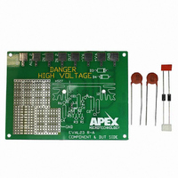
... EK28 FIGURE 2. PCB TOP SIDE IC BOTTOM SIDE DANGER D3 HIGH VOLTAGE HS27 LIM GND GND MICROTECHNOLOGY EVAL23 R-A COMPONENT & DUT SIDE 4. 3. EK28U ...
Page 3
... Cirrus Logic, Cirrus, and the Cirrus Logic logo designs, Apex Precision Power, Apex and the Apex Precision Power logo designs are trademarks of Cirrus Logic, Inc. All other brand and product names in this document may be trademarks or service marks of their respective owners. EK28U EK28 3 ...