AD8224-EVALZ Analog Devices Inc, AD8224-EVALZ Datasheet - Page 7
AD8224-EVALZ
Manufacturer Part Number
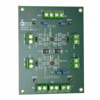
AD8224-EVALZ
Description
BOARD EVALUATION AD8224
Manufacturer
Analog Devices Inc
Specifications of AD8224-EVALZ
Channels Per Ic
2 - Dual
Amplifier Type
Instrumentation
Output Type
Single-Ended, Rail-to-Rail
Slew Rate
2 V/µs
-3db Bandwidth
1.5MHz
Current - Output / Channel
15mA
Operating Temperature
-40°C ~ 85°C
Current - Supply (main Ic)
750µA
Voltage - Supply, Single/dual (±)
4.5 V ~ 36 V, ±2.25 V ~ 18 V
Board Type
Fully Populated
Utilized Ic / Part
AD8224
Silicon Manufacturer
Analog Devices
Application Sub Type
JFET Input Instrumentation Amplifier
Kit Application Type
Amplifier
Silicon Core Number
AD8224
Kit Contents
Board
Lead Free Status / RoHS Status
Lead free / RoHS Compliant
Available stocks
Company
Part Number
Manufacturer
Quantity
Price
Company:

Part Number:
AD8224-EVALZ
Manufacturer:
Analog Devices Inc
Quantity:
135


Parameter
GAIN
INPUT
OUTPUT
POWER SUPPLY (PER AMPLIFIER)
TEMPERATURE RANGE
1
2
3
4
5
6
When the output sinks more than 4 mA, use a 47 pF capacitor in parallel with the load to prevent ringing. Otherwise, use a larger load, such as 10 kΩ.
Refers to the differential configuration shown in
Refer to
Differential and common-mode impedance can be calculated from the pin impedance: Z
The AD8224 can operate up to a diode drop below the negative supply, but the bias current increases sharply. The input voltage range reflects the maximum
allowable voltage where the input bias current is within the specification.
The AD8224 is characterized from −40°C to +125°C. See the
Gain Range
Gain Error
Nonlinearity
Gain vs. Temperature
Impedance (Pin to Ground)
Input Voltage Range
Output Swing
Output Swing
Short-Circuit Current
Operating Range
Quiescent Current
For Specified Performance
Operational
G = 1
G = 10
G = 100
G = 1000
G = 1
G = 10
G = 100
G = 1000
G = 1
G = 10
G = 100
G = 1000
G = 1
G > 10
Over Temperature
Over Temperature
Over Temperature
Over Temperature
Figure 14
6
and
Figure 15
5
for the relationship between input current and temperature.
4
Figure 63
T = −40°C to +85°C
Test Conditions
G = 1 + (49.4 kΩ/R
V
V
V
V
V
V
R
R
R
R
R
R
R
R
R
T = −40°C to +85°C
R
T = −40°C to +85°C
T = −40°C to +85°C
OUT
OUT
OUT
OUT
OUT
OUT
L
L
L
L
L
L
L
L
L
L
= 10 kΩ
= 10 kΩ
= 10 kΩ
= 10 kΩ
= 2 kΩ
= 2 kΩ
= 2 kΩ
= 2 kΩ
= 2 kΩ
= 10 kΩ
= 0.3 V to 2.9 V for G = 1
= 0.3 V to 3.8 V for G > 1
.
= 0.3 V to 2.9 V
= 0.3 V to 3.8 V
= 0.3 V to 3.8 V
= 0.3 V to 3.8 V
Typical Performance Characteristics
Rev. B | Page 7 of 28
G
)
Min
1
−0.1
−0.1
0.25
0.3
0.15
0.2
4.5
−40
−40
DIFF
= 2(Z
section for expected operation in that temperature range.
Typ
35
35
50
90
35
35
50
175
3
10
15
750
850
PIN
A Grade
); Z
4
||6
CM
= Z
PIN
Max
1000
0.06
0.3
0.3
0.3
50
50
75
115
50
50
75
200
10
−50
+V
+V
4.75
4.70
4.85
4.80
36
800
900
+85
+125
/2.
S
S
− 2
− 2.1
Min
1
−0.1
−0.1
0.25
0.3
0.15
0.2
4.5
−40
−40
Typ
35
35
50
90
35
35
50
175
2
10
15
750
850
B Grade
4
||6
Max
1000
0.04
0.2
0.2
0.2
50
50
75
115
50
50
75
200
5
−50
+V
+V
4.75
4.70
4.85
4.80
36
800
900
+85
+125
S
S
− 2
− 2.1
AD8224
Unit
V/V
%
%
%
%
ppm
ppm
ppm
ppm
ppm
ppm
ppm
ppm
ppm/°C
ppm/°C
GΩ||pF
V
V
V
V
V
V
mA
V
μA
μA
°C
°C
Related parts for AD8224-EVALZ
Image
Part Number
Description
Manufacturer
Datasheet
Request
R

Part Number:
Description:
Single Supply, Rail to Rail Low Power FET-Input Op Amp
Manufacturer:
Analog Devices
Datasheet:

Part Number:
Description:
±1.7g Dual-Axis IMEMS Accelerometer Evaluation Board
Manufacturer:
Analog Devices Inc
Datasheet:

Part Number:
Description:
Inertial Sensor Evaluation System
Manufacturer:
Analog Devices Inc
Datasheet:
Part Number:
Description:
Manufacturer:
Analog Devices Inc
Datasheet:
Part Number:
Description:
Manufacturer:
Analog Devices Inc
Datasheet:
Part Number:
Description:
Manufacturer:
Analog Devices Inc
Datasheet:
Part Number:
Description:
Manufacturer:
Analog Devices Inc
Datasheet:
Part Number:
Description:
Manufacturer:
Analog Devices Inc
Datasheet:
Part Number:
Description:
Manufacturer:
Analog Devices Inc
Datasheet:
Part Number:
Description:
Manufacturer:
Analog Devices Inc
Datasheet:
Part Number:
Description:
Manufacturer:
Analog Devices Inc
Datasheet:
Part Number:
Description:
Manufacturer:
Analog Devices Inc
Datasheet:
Part Number:
Description:
Manufacturer:
Analog Devices Inc
Datasheet: