AD8336-EVALZ Analog Devices Inc, AD8336-EVALZ Datasheet - Page 23
AD8336-EVALZ
Manufacturer Part Number
AD8336-EVALZ
Description
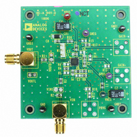
BOARD EVALUATION FOR AD8336
Manufacturer
Analog Devices Inc
Series
X-AMP®r
Specifications of AD8336-EVALZ
Channels Per Ic
1 - Single
Amplifier Type
Variable Gain
Output Type
Single-Ended
Slew Rate
550 V/µs
-3db Bandwidth
115MHz
Current - Output / Channel
20mA
Operating Temperature
-55°C ~ 125°C
Current - Supply (main Ic)
28mA
Voltage - Supply, Single/dual (±)
±3 V ~ 12 V
Board Type
Fully Populated
Utilized Ic / Part
AD8336
Silicon Manufacturer
Analog Devices
Application Sub Type
Variable Gain Amplifier
Kit Application Type
Amplifier
Silicon Core Number
AD8336
Kit Contents
Board
Lead Free Status / RoHS Status
Lead free / RoHS Compliant
Available stocks
Company
Part Number
Manufacturer
Quantity
Price
Company:

Part Number:
AD8336-EVALZ
Manufacturer:
Analog Devices Inc
Quantity:
135


GAIN = 9.6dB INPN
Circuit Configuration for Inverting Gain
The preamplifier can also be used in an inverting configuration,
as shown in Figure 81.
The considerations regarding total resistance vs. distortion, noise,
and power that were noted in the noninverting case also apply
in the inverting case, except that the amplifier can be operated
at unity inverting gain. The signal gain is reduced while the
noise gain is the same as for the noninverting configuration:
and
R
100Ω
FB1
Signal
Noise
R
301Ω
FB2
INPP
Figure 81. Circuit Configuration for Inverting Gain
Gain
Gain
4
5
8
=
=
PRAO
PREAMPLIFIER
+
–
R
R
R
R
FB2
FB1
AD8336
FB2
FB1
VGAI
+
1
9
–60dB TO 0dB
PWRA
2
VNEG
–5V
10
VCOM
3
34dB
VPOS
+5V
13
1
VOUT
Rev. A | Page 23 of 28
USING THE POWER ADJUST FEATURE
The AD8336 has the provision to operate at lower power with
a trade-off in bandwidth. The power reduction applies to the
preamp and the VGA sections, and the bandwidth is reduced
equally between them. Reducing the power is particularly useful
when operating with higher supply voltages and lower values of
output loading that would otherwise stress the output amplifiers.
When Pin PWRA is grounded, the amplifiers operate in their
default mode, and the combined 3 dB bandwidth is 80 MHz
with the preamp gain adjusted to 4×. When the voltage on
Pin PWRA is between 1.2 V and 5 V, the power is reduced by
approximately half and the 3 dB bandwidth reduces to
approximately 35 MHz. The voltage at Pin PWRA must not
exceed 5 V.
DRIVING CAPACITIVE LOADS
The output stages of the AD8336 are stable with capacitive loads
up to 47 pF for a supply voltage of ±3 V and with capacitive loads
up to 10 pF for supply voltages up to ±8 V. For larger combined
values of load capacitance and/or supply voltage, a 20 Ω series
resistor is recommended for stability.
The influence of capacitance and supply voltage are shown in
Figure 50 and Figure 51, where representative combinations of
load capacitance and supply voltage requiring a 20 Ω resistor
are marked with an asterisk. No resistor is required for the ±3 V
plots in Figure 49, but a resistor is required for most of the ±12 V
plots in Figure 51.
AD8336
Related parts for AD8336-EVALZ
Image
Part Number
Description
Manufacturer
Datasheet
Request
R

Part Number:
Description:
±1.7g Dual-Axis IMEMS Accelerometer Evaluation Board
Manufacturer:
Analog Devices Inc
Datasheet:

Part Number:
Description:
Inertial Sensor Evaluation System
Manufacturer:
Analog Devices Inc
Datasheet:
Part Number:
Description:
Manufacturer:
Analog Devices Inc
Datasheet:
Part Number:
Description:
Manufacturer:
Analog Devices Inc
Datasheet:
Part Number:
Description:
Manufacturer:
Analog Devices Inc
Datasheet:
Part Number:
Description:
Manufacturer:
Analog Devices Inc
Datasheet:
Part Number:
Description:
Manufacturer:
Analog Devices Inc
Datasheet:
Part Number:
Description:
Manufacturer:
Analog Devices Inc
Datasheet:
Part Number:
Description:
Manufacturer:
Analog Devices Inc
Datasheet:
Part Number:
Description:
Manufacturer:
Analog Devices Inc
Datasheet:
Part Number:
Description:
Manufacturer:
Analog Devices Inc
Datasheet:
Part Number:
Description:
Manufacturer:
Analog Devices Inc
Datasheet:
Part Number:
Description:
Manufacturer:
Analog Devices Inc
Datasheet: