AS5145 DB austriamicrosystems, AS5145 DB Datasheet - Page 22
AS5145 DB
Manufacturer Part Number
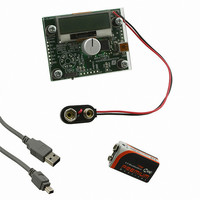
AS5145 DB
Description
BOARD DEMO AS5145
Manufacturer
austriamicrosystems
Specifications of AS5145 DB
Sensor Type
Magnetic, Rotary Position
Sensing Range
360°
Interface
USB
Voltage - Supply
5V USB or 9V
Embedded
Yes, MCU, 8-Bit
Utilized Ic / Part
AS5145
Lead Free Status / RoHS Status
Lead free by exemption / RoHS compliant by exemption
Sensitivity
-


AS5145
Data Sheet - A p p l i c a t i o n I n f o r m a t i o n
9.1.6 Redundant Programming Option
In addition to the regular programming, a redundant programming option is available. This option allows that one selectable OTP bit can be set
to “1” (programmed state) by writing the location of that bit into a 5-bit address decoder. This address can be stored in bits RA4..RA0 in the OTP
user settings.
Example: setting RA4…0 to “00001” will select bit 51 = PWhalfEN_Indexwidth, “00010” selects bit 50 = MagCompEN, “10010” selects bit 34
=CCW, etc.
9.1.7 OTP Register Entry and Exit Condition
Figure 13. OTP Access Timing Diagram
To avoid accidental modification of the OTP during normal operation, each OTP access (Load, Write, Read, Program) requires a defined entry
and exit procedure, using the CSn, PDIO and CLK signals as shown in
Figure 14. OTP Programming Connection
www.austriamicrosystems.com/AS5145
10n
PDIO
CSn
CLK
Cap only required for
OTP programming
1
2
3
4
5
6
7
8
Mode_Index
MagINCn
MagDECn
DTest1_A
DTest2_B
NC
VSS
PDIO
AS5145
IC1
VDD3V3
VDD5V
PWM
CSn
Setup Condition
CLK
DO
NC
NC
16
15
14
13
12
11
10
9
2.2µF
Operation Mode Selection
max. length = 2 inches (5cm)
as short as possible!
keep these 6 wires
For programming,
22k
*see Text
Revision 1.11
Figure
7
6
5
4
3
2
1
13.
PROG
CSN
DO
CLK
5VUSB
VDD3V3
VSS
AS5145 Demoboard
OTP Access
GND
µC
3V3
Exit Condition
3
2
1
connect to USB
interface on PC
3.3 … 4.6 V
only required for
OTP programming
VPROG
VSS
+
10µF
GND
22 - 36
Related parts for AS5145 DB
Image
Part Number
Description
Manufacturer
Datasheet
Request
R

Part Number:
Description:
BOARD ADAPTER AS5145
Manufacturer:
austriamicrosystems
Datasheet:

Part Number:
Description:
IC ENCODER PROG 12-BIT 16-SSOP
Manufacturer:
austriamicrosystems
Datasheet:
Part Number:
Description:
IC ENCODER PROG 12-BIT 16-SSOP
Manufacturer:
austriamicrosystems
Datasheet:
Part Number:
Description:
12 Bit Programmable Magnetic Rotary Encoder
Manufacturer:
austriamicrosystems
Datasheet:
Part Number:
Description:
IC SWITCH QUAD SPST 14-TSSOP
Manufacturer:
austriamicrosystems
Datasheet:
Part Number:
Description:
IC SWITCH QUAD SPST 14-TSSOP
Manufacturer:
austriamicrosystems
Datasheet:
Part Number:
Description:
IC AMP AUDIO MONO 1.8W 10-MSOP
Manufacturer:
austriamicrosystems
Datasheet:
Part Number:
Description:
IC AMP AUDIO MONO 1.8W 10-MSOP
Manufacturer:
austriamicrosystems
Datasheet:
Part Number:
Description:
IC AMP AUDIO MONO 1.8W 10-MSOP
Manufacturer:
austriamicrosystems
Datasheet:
Part Number:
Description:
IC AMP AUD 1.8W 3DB GAIN 10-MSOP
Manufacturer:
austriamicrosystems
Datasheet:
Part Number:
Description:
IC DRIVER LED 8-DIGIT 24-SOIC
Manufacturer:
austriamicrosystems
Datasheet:
Part Number:
Description:
IC DRIVER LED 8-DIGIT 24-SOIC
Manufacturer:
austriamicrosystems
Datasheet:
Part Number:
Description:
IC, LINE/SPEAKER PHONE CIRCUIT, SOIC-28
Manufacturer:
austriamicrosystems
Datasheet:
Part Number:
Description:
IC MULTI-STANDARD CMOS TELEPHONE SOIC-28
Manufacturer:
austriamicrosystems
Datasheet:
Part Number:
Description:
IC MULTI-STANDARD CMOS TELEPHONE SOIC-28
Manufacturer:
austriamicrosystems
Datasheet: