MCP9800DM-DL2 Microchip Technology, MCP9800DM-DL2 Datasheet - Page 27
MCP9800DM-DL2
Manufacturer Part Number
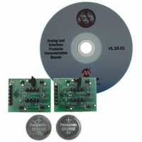
MCP9800DM-DL2
Description
BOARD DEMO 2 FOR MCP9800
Manufacturer
Microchip Technology
Datasheets
1.MCP9800A0T-MOT.pdf
(42 pages)
2.MCP9800A0T-MOT.pdf
(4 pages)
3.MCP9800DM-DL2.pdf
(22 pages)
4.MCP9801-MSN.pdf
(30 pages)
Specifications of MCP9800DM-DL2
Sensor Type
Temperature
Sensing Range
-55°C ~ 125°C
Interface
I²C, SMBus
Sensitivity
±0.5°C
Voltage - Supply
2.7 V ~ 5.5 V
Embedded
Yes, MCU, 8-Bit
Utilized Ic / Part
MCP9800
Processor To Be Evaluated
MCP9800, MCP101, PIC10F202, 24LC16B
Interface Type
I2C
Lead Free Status / RoHS Status
Not applicable / Not applicable


6.0
6.1
The SDA and SCL serial interface are open-drain pins
that require pull-up resistors. This configuration is
shown in
FIGURE 6-1:
Interface.
The MCP9800/1/2/3 is designed to meet 0.4V
(maximum) voltage drop at 3 mA of current. This allows
the MCP9800/1/2/3 to drive lower values of pull-up
resistors and higher bus capacitance. In this
application, all devices on the bus must meet the same
pull-down current requirements.
6.2
Microchip provides several microcontroller product
lines with Master Synchronous Serial Port modules
(MSSP) that include the I
module implements all master and slave functions and
simplifies
Figure 6-2
PIC16F737 as a master to control other Microchip
slave products, such as EEPROM, fan speed
controllers and the MCP9800 temperature sensor
connected to the bus.
FIGURE 6-2:
Bus.
2010 Microchip Technology Inc.
Microcontroller
APPLICATIONS INFORMATION
Connecting to the Serial Bus
Typical Application
PIC
MCU
Figure
PIC16F737
Fan Speed
Controller
the
shows a typical application using the
TC654
®
6-1.
firmware
Pull-up Resistors on Serial
Multiple Devices on I
SDA SCL
V
R
DD
2
development
C interface mode. This
R
Temperature
MCP9800/1/2/3
EEPROM
SDA
SCL
TCN75A
24LC01
Sensor
overhead.
2
C™
The ALERT output can be wired with a number of other
open-drain devices. In such applications, the output
needs to be programmed as an active-low output. Most
systems
configuration.
6.3
The MCP9800/1/2/3 does not require any additional
components besides the master controller in order to
measure temperature. However, it is recommended
that a decoupling capacitor of 0.1 µF to 1 µF be used
between the V
ceramic capacitor is recommended. It is necessary for
the capacitor to be located as close as possible to the
power pins in order to provide effective noise
protection.
For applications where a switching regulator is used to
power the sensor, it is recommended to add a 200Ω
resistor in series to V
from the sensor. It is also recommended to add the
series resistor in applications where a linear regulator
is used to step-down a switching regulator voltage to
power the sensor. For example, if a linearly regulated
3.3V from a 5V switching regulator is used to power the
sensor, add a 200Ω series resistor (refer to
FIGURE 6-3:
Single Resistor.
6.4
The
monitoring the voltage of a diode located in the die. A
low-impedance thermal path between the die and the
Printed Circuit Board (PCB) is provided by the pins.
Therefore, the MCP9800/1/2/3 effectively monitors the
temperature of the PCB. However, the thermal path for
the ambient air is not as efficient because the plastic
device package functions as a thermal insulator.
A potential for self-heating errors can exist if the
MCP9800/1/2/3 SDA and SCL communication lines
are heavily loaded with pull-ups. Typically, the
self-heating error is negligible because of the relatively
small current consumption of the MCP9800/1/2/3.
However, in order to maximize the temperature
accuracy, the SDA and SCL pins need to be lightly
loaded.
Switching
Regulator
Switching
Regulator
MCP9800/1/2/3
Layout Considerations
Thermal Considerations
will
DD
MCP9800/1/2/3
require
Regulator
Linear
and GND pins. A high-frequency
DD
200
Power-supply Filter Using a
to filter out the switcher noise
measures
bypass
pull-up
0.1 µF
bypass
0.1 µF
200
MCP9800/1/2/3
resistors
DS21909D-page 27
MCP9800/1/2/3
temperature
V
DD
V
DD
Figure
for
6-3).
this
by
Related parts for MCP9800DM-DL2
Image
Part Number
Description
Manufacturer
Datasheet
Request
R

Part Number:
Description:
Manufacturer:
Microchip Technology, Inc.
Datasheet:

Part Number:
Description:
(MCP9800 - MCP9803) 2-Wire High-Accuracy Temperature Sensor
Manufacturer:
Microchip Technology
Datasheet:

Part Number:
Description:
Manufacturer:
Microchip Technology Inc.
Datasheet:
Part Number:
Description:
Manufacturer:
Microchip Technology Inc.
Datasheet:
Part Number:
Description:
Manufacturer:
Microchip Technology Inc.
Datasheet:
Part Number:
Description:
Manufacturer:
Microchip Technology Inc.
Datasheet:
Part Number:
Description:
Manufacturer:
Microchip Technology Inc.
Datasheet:
Part Number:
Description:
Manufacturer:
Microchip Technology Inc.
Datasheet:
Part Number:
Description:
Manufacturer:
Microchip Technology Inc.
Datasheet:
Part Number:
Description:
Manufacturer:
Microchip Technology Inc.
Datasheet: