MCP6SX2DM-PCTLTH Microchip Technology, MCP6SX2DM-PCTLTH Datasheet - Page 23
MCP6SX2DM-PCTLTH
Manufacturer Part Number
MCP6SX2DM-PCTLTH
Description
BOARD DEMO PICTAIL THERM MCP6SX2
Manufacturer
Microchip Technology
Series
PICtail™r
Datasheets
1.AC164120.pdf
(36 pages)
2.MCP6SX2DM-PCTLTH.pdf
(32 pages)
3.MCP6SX2DM-PCTLPD.pdf
(12 pages)
Specifications of MCP6SX2DM-PCTLTH
Sensor Type
Thermistor
Interface
Analog
Voltage - Supply
2.5 V ~ 5.5 V
Embedded
No
Utilized Ic / Part
MCP6S22, MCP6S92
Processor To Be Evaluated
MCP6Sx2
Lead Free Status / RoHS Status
Contains lead / RoHS non-compliant
Sensitivity
-
Sensing Range
-
Lead Free Status / Rohs Status
Lead free / RoHS Compliant
Available stocks
Company
Part Number
Manufacturer
Quantity
Price
Company:

Part Number:
MCP6SX2DM-PCTLTH
Manufacturer:
MICROCHIP
Quantity:
12 000


A.1
A.2
© 2006 Microchip Technology Inc.
INTRODUCTION
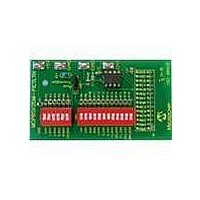
DEMONSTRATION BOARD DESCRIPTION
This appendix contains the schematics and layouts for the MCP6SX2 PGA Thermistor
PICtail™ Demo Board.
The MCP6SX2-PICTLTH demonstration board is constructed using a two-layer Printed
Circuit Board (PCB). The top layer is for components and traces, while the bottom layer
is the ground plane.
Information on this board includes:
• Board Schematic
• Board - Top Silk-Screen And Metal Layers
• Board - Top Metal Layer
• Board - Bottom Metal Layer
A simplified block diagram of this board is shown in Figure 1-1. The detailed schematic
is given in Figure A.4.
DIP switch SW
in Figure 3-1). R
together. Resistors R
32.0 kΩ.
R
DIP switch SW
thermistor. Rvar produces a binary sequence between 0Ω and 409.5 kΩ.
The jumper JMP
low-pass analog filters used to minimize noise. They also act as anti-aliasing filters for
the ADC.
U
PGA buffers the transimpedance amplifier output and makes it possible to gain up
weak signals before conversion by the ADC. J
Analysis board. C
The demonstration board includes test points for convenience on the bench. The +5V
and GND test points connect to the board’s supply voltages. The CH0 test point
connects to the PGA’s CH0 input; it is also connected to the voltage divider’s output
(with filtering). The CH1 test point allows the user to place any desired signal at the
PGA’s CH1 input.
Appendix A. Schematic and Layouts
21
1
Note:
is either the MCP6S22 or the MCP6S92 Programmable Gain Amplifier (PGA). The
is the thermistor (R
While headers J1, J2, and J3 are shown together in the schematic (see
Figure A.4), J2 is installed (see Table B-1), while J1 and J3 are not. J2 and
J3 are placeholders only.
MCP6SX2 PGA THERMISTOR PICtail™
1
2
and resistors R
1
1
and resistors R
2
selects either the thermistor or its emulator Rvar. R
is placed in series with the others to prevent shorting the supplies
and C
1
– R
TH
3
7
in Figure 3-1).
are bypass capacitors that minimize power supply noise.
produce a binary sequence of values between 0.5 kΩ and
DEMO BOARD USER’S GUIDE
1
8
– R
– R
7
19
emulate the voltage divider’s series resistor (R
(labeled Rvar in top silk screen) emulate the
2
connects this board to the Signal
20
DS51517B-page 19
and C
1
are the
A
Related parts for MCP6SX2DM-PCTLTH
Image
Part Number
Description
Manufacturer
Datasheet
Request
R

Part Number:
Description:
BOARD DAUGHTER PICTAIL MCP6SX2
Manufacturer:
Microchip Technology
Datasheet:

Part Number:
Description:
Manufacturer:
Microchip Technology Inc.
Datasheet:
Part Number:
Description:
Manufacturer:
Microchip Technology Inc.
Datasheet:
Part Number:
Description:
Manufacturer:
Microchip Technology Inc.
Datasheet:
Part Number:
Description:
Manufacturer:
Microchip Technology Inc.
Datasheet:
Part Number:
Description:
Manufacturer:
Microchip Technology Inc.
Datasheet:
Part Number:
Description:
Manufacturer:
Microchip Technology Inc.
Datasheet:
Part Number:
Description:
Manufacturer:
Microchip Technology Inc.
Datasheet:
Part Number:
Description:
Manufacturer:
Microchip Technology Inc.
Datasheet: