AMT303-DMK CUI Inc, AMT303-DMK Datasheet - Page 7
AMT303-DMK
Manufacturer Part Number
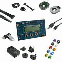
AMT303-DMK
Description
DEMO KIT AMT303-V ENCODERS
Manufacturer
CUI Inc
Series
AMT303r
Specifications of AMT303-DMK
Sensor Type
Encoders, Capacitive
Sensing Range
360°
Interface
SPI, Incremental with Index
Sensitivity
1024 PPR
Voltage - Supply
2.7 V ~ 5.5 V
Embedded
No
Utilized Ic / Part
AMT303
Lead Free Status / RoHS Status
Lead free / RoHS Compliant
Other names
102-2053


PART NUMBER:
Command 0x70: set_zero_point
This command sets the current position to zero or adjusts to the offset stored in comm_pos in the EEPROM and
saves this setting in the EEPROM. The host should send nop_a5 repeatedly after sending this command, the
response will be 0xa5 while update is proceeding and eeprom_wr is the response when update is finished. 0xF9 is
the location for the Low Byte of comm_pos and 0xF8 is the location for the High Byte of comm_pos.
Comand 0x80,<byte_address>,<data>: eeprom_wr
This command causes the data to be written to the address given in <byte_address>. The address can be 0x00 to
0x7f for 128 bytes of data.
Comand 0x90,<byte_address>,0x01: eeprom_rd
This command causes the data in eeprom at the given address to be read and put in the output fifo.
The sequence is as follows:
1) issue read command, receive idle character
2) issue NOP, receive idle character or 0x90 (echo of read command)
3) repeat step 2 if it is an idle character
4) issue NOP and receive
Commutation Alignment and setting the Zero point
To align the commutation angle with the encoder there are two steps:
1) Configure the encoder alignment angle using the Demo Board. The alignment angle is the angle relative to
2) With the encoder mounted, position the rotor to the alignment angle and use the “zero” command on the demo
Note: the demo board allows setting the alignment angle between -180 and 180 degrees in increments of
U,V,W poles which is used for setting the encoder on the armature. The alignment angle is set at the same time
as several other parameters, and the encoder must be power cycled after configuration.
board to write the rotor position in non-volatile memory in the encoder. The encoder must be power cycled after
this operation, and it will use this offset at initialization every time at startup.
5 degrees. 0 (zero) degrees corresponds to the rising edge of the U signal. The direction of rotation can also
be set.
20050 SW 112
AMT303
th
Ave. Tualatin, Oregon 97062
phone 503.612.2300
DESCRIPTION:
fax 503.612.2380 www.cui.com
COMMUTATION ENCODER
date
page
12/2010
7 of 7
Related parts for AMT303-DMK
Image
Part Number
Description
Manufacturer
Datasheet
Request
R

Part Number:
Description:
KIT AMT303 COMM SPI ENCODER
Manufacturer:
CUI Inc
Datasheet:

Part Number:
Description:
PROG ENCODER CW 96PPR 2POLE
Manufacturer:
CUI Inc
Datasheet:
Part Number:
Description:
PROG ENCODER CW 192PPR 2POLE
Manufacturer:
CUI Inc
Datasheet:
Part Number:
Description:
PROG ENCODER CW 200PPR 2POLE
Manufacturer:
CUI Inc
Datasheet:
Part Number:
Description:
PROG ENCODER CW 250PPR 2POLE
Manufacturer:
CUI Inc
Datasheet:
Part Number:
Description:
PROG ENCODER CW 400PPR 2POLE
Manufacturer:
CUI Inc
Datasheet:
Part Number:
Description:
PROG ENCODER CW 500PPR 2POLE
Manufacturer:
CUI Inc
Datasheet:
Part Number:
Description:
PROG ENCODER CW 512PPR 2POLE
Manufacturer:
CUI Inc
Datasheet:
Part Number:
Description:
PROG ENCODER CW 800PPR 2POLE
Manufacturer:
CUI Inc
Datasheet:
Part Number:
Description:
PROG ENCODER CW 1000PPR 2POLE
Manufacturer:
CUI Inc
Datasheet:

Part Number:
Description:
SPEAKER ALNICO 8OHM 2W 100MM SQR
Manufacturer:
CUI Inc
Datasheet:

Part Number:
Description:
ac-dc converter
Manufacturer:
CUI [CUI INC]
Datasheet:
Part Number:
Description:
MEDICAL SWITCHING POWER SUPPLY
Manufacturer:
CUI [CUI INC]
Datasheet:
Part Number:
Description:
DC-DC Converter
Manufacturer:
CUI [CUI INC]
Datasheet:
Part Number:
Description:
DC/DC Converter
Manufacturer:
CUI [CUI INC]
Datasheet: