AT91SAM7S-EK Atmel, AT91SAM7S-EK Datasheet - Page 12
AT91SAM7S-EK
Manufacturer Part Number
AT91SAM7S-EK
Description
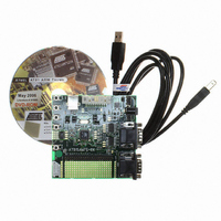
KIT EVAL FOR ARM AT91SAM7S
Manufacturer
Atmel
Series
AT91SAM Smart ARMr
Type
MCUr
Datasheet
1.AT91SAM7S-EK.pdf
(27 pages)
Specifications of AT91SAM7S-EK
Contents
Evaluation Board, Parallel Cable and CD-ROM
Processor To Be Evaluated
AT91SAM7S
Data Bus Width
32 bit
Interface Type
USB
Silicon Manufacturer
Atmel
Core Architecture
ARM
Core Sub-architecture
ARM7TDMI
Silicon Core Number
AT91SAM7S
Silicon Family Name
ARM
Kit Contents
Board CD Docs
For Use With/related Products
AT91SAM7S
Lead Free Status / RoHS Status
Contains lead / RoHS non-compliant
Available stocks
Company
Part Number
Manufacturer
Quantity
Price
Company:

Part Number:
AT91SAM7S-EK
Manufacturer:
Atmel
Quantity:
135


6112C–ATARM–01-Feb-07
Board Description
3.5
3.6
3.7
3.8
3.9
3.10
3.11
3.12
3-4
Reset Circuitry
Power Supply
Circuitry
Remote
Communication
Analog Interface
User Interface
Debug Interface
Expansion
Connector
Wrapping User
Area
! Internal bi-directional reset controller with brown out detector
! External reset pushbutton
! USB powered. The dynamic power consumption on VDDCORE is less than 50 mA at
! External power can be applied via the 2.1 mm connector to the regulator in either
! The two power supplies are separated from each other by the diodes CR1 and CR2.
! On-chip embedded VDDCORE 1.8V regulator
! Two serial interface via RS-232 DB9 male sockets
! USB V2.0 full-speed compliant, 12 Mbits per second (UDP)
! Four analog inputs (0V to 3.3V) via J7, J8, J9, J10 footprints
! Four pushbuttons via general PIO lines
! Four LEDs via high current PIO lines
! 20-pin JTAG/ICE interface connector
! DBGU COM port
One expansion connector (J5) gives access to all the microcontroller's signals.
All I/Os of the AT91SAM7S256 are routed to this connector. This allows the developer
to check the integrity of the components and to extend the features of the board by add-
ing external hardware components or boards.
This allows the developer to fit additional components for prototyping use.
full speed when running out of the Flash. The total current drawn by all the I/O lines
cannot exceed 200 mA.
polarity because of the diode-rectifying circuit (CR3 to CR6). The minimum voltage
required is 7V. The board has a voltage regulator providing +3.3V. The regulator
allows the input voltage to be from 7V to 14V (REG1).
– DBGU COM Port
– UART COM Port with RTS/CTS handshake control possibility (USART 0)
AT91SAM7S-EK Evaluation Board User Guide
Related parts for AT91SAM7S-EK
Image
Part Number
Description
Manufacturer
Datasheet
Request
R

Part Number:
Description:
MCU ARM9 64K SRAM 144-LFBGA
Manufacturer:
Atmel
Datasheet:

Part Number:
Description:
IC ARM7 MCU FLASH 256K 100LQFP
Manufacturer:
Atmel
Datasheet:

Part Number:
Description:
IC ARM9 MPU 217-LFBGA
Manufacturer:
Atmel
Datasheet:
Part Number:
Description:
MCU ARM9 ULTRA LOW PWR 217-LFBGA
Manufacturer:
Atmel
Datasheet:

Part Number:
Description:
MCU ARM9 324-TFBGA
Manufacturer:
Atmel
Datasheet:
Part Number:
Description:
IC MCU ARM9 SAMPLING 217CBGA
Manufacturer:
Atmel
Datasheet:
Part Number:
Description:
IC ARM9 MCU 217-LFBGA
Manufacturer:
Atmel
Datasheet:

Part Number:
Description:
IC ARM9 MCU 208-PQFP
Manufacturer:
Atmel
Datasheet:
Part Number:
Description:
MCU ARM 512K HS FLASH 100-LQFP
Manufacturer:
Atmel
Datasheet:

Part Number:
Description:
MCU ARM 512K HS FLASH 100-TFBGA
Manufacturer:
Atmel
Datasheet:
Part Number:
Description:
IC ARM9 MCU 200 MHZ 324-TFBGA
Manufacturer:
Atmel
Datasheet:

Part Number:
Description:
IC ARM MCU 16BIT 128K 256BGA
Manufacturer:
Atmel
Datasheet:

Part Number:
Description:
IC ARM7 MCU 32BIT 128K 64LQFP
Manufacturer:
Atmel
Datasheet:

Part Number:
Description:
IC ARM7 MCU FLASH 256K 128-LQFP
Manufacturer:
Atmel
Datasheet:
Part Number:
Description:
IC ARM7 MCU FLASH 512K 128-LQFP
Manufacturer:
Atmel
Datasheet: