DK-MAXII-1270N Altera, DK-MAXII-1270N Datasheet - Page 33
DK-MAXII-1270N
Manufacturer Part Number
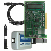
DK-MAXII-1270N
Description
KIT DEV MAXII W/EPM 1270N
Manufacturer
Altera
Series
MAX® IIr
Type
CPLDr
Specifications of DK-MAXII-1270N
Contents
Dev Board, Quartus®II Web Edition, Nios®II Web Edition, Cables, Accessories, Reference Designs and Demos
Silicon Manufacturer
Altera
Core Architecture
CPLD
Core Sub-architecture
MAX
Silicon Core Number
EPM
Silicon Family Name
MAX II
Rohs Compliant
Yes
For Use With/related Products
MAX®II CPLDs
Lead Free Status / RoHS Status
Lead free / RoHS Compliant
Other names
544-2380
Available stocks
Company
Part Number
Manufacturer
Quantity
Price


Altera Corporation
July 2005
■
■
■
When the values have been calculated and mapped, the Registers block
(see
then uses the MUX function to access the flash memory block (for
simulated spinning action of the reel), and the Register block (to display
the final bankroll and reel values). Upon completion of this process, the
design cycles back to monitor the status of the Bet signal to prepare for
another spin.
LCD Controller
The MAX II Slot Game Reference Design communicates with the
on-board LCD through a custom-built controller interface. The logic
block performs several functions vital to the game behavior. Upon
successful programming of the device, the block sequentially loads a
series of specific codes that initialize the LCD hardware and configure the
display environment. When initialization is complete, it interprets 11-bit
instructions fed by the design’s Control block, and manages the delivery
of characters to be displayed on the screen. Based on the value of the
11-bit input bus, the controller handles changes to the speed, content, and
direction (read/write) of LCD data.
Figure
Start-up—When the MAX II device has been successfully
programmed, the Control block automatically accesses a section of
the UFM that prompts an introduction sequence to appear on the
LCD screen. This sequence loops indefinitely until a player presses
the Bet button to begin game play.
Bet Selection—The Bet button provides access to three separate
memory spaces within the UFM, representing the three fixed wager
amounts. Each time the button is pressed, a memory pointer cycles
to the next space in the sequence, displaying the corresponding
wager amount on the LCD screen. The Control block keeps track of
the memory pointer, and thus can cycle through the three wager
values repeatedly.
Spin Engagement—When the Spin button is toggled, the Control
block state machine is sent through a series of actions that affect the
final display of the LCD. First the LFSR is sampled and three
pseudo-random values are generated from its output. Based on the
commonality of these values, a new bankroll total is calculated and
stored internally. This total is then divided into three separate values
that represent the Hundreds, Tens, and Ones place of the number.
These values, along with the LSFR generated values for each reel, are
mapped to 11-bit codes that prompt the LCD to display the correct
number value.
Development Kit Version 1.1.0
2–8) is updated with new bankroll and reel values. The block
MAX II Development Kit Getting Started User Guide
Getting Started
2–25
Related parts for DK-MAXII-1270N
Image
Part Number
Description
Manufacturer
Datasheet
Request
R

Part Number:
Description:
KIT DEV MAX V 5M570Z
Manufacturer:
Altera
Datasheet:

Part Number:
Description:
CYCLONE II STARTER KIT EP2C20N
Manufacturer:
Altera
Datasheet:


Part Number:
Description:
CPLD, EP610 Family, ECMOS Process, 300 Gates, 16 Macro Cells, 16 Reg., 16 User I/Os, 5V Supply, 35 Speed Grade, 24DIP
Manufacturer:
Altera Corporation
Datasheet:
Part Number:
Description:
CPLD, EP610 Family, ECMOS Process, 300 Gates, 16 Macro Cells, 16 Reg., 16 User I/Os, 5V Supply, 15 Speed Grade, 24DIP
Manufacturer:
Altera Corporation
Datasheet:
Part Number:
Description:
Manufacturer:
Altera Corporation
Datasheet:
Part Number:
Description:
CPLD, EP610 Family, ECMOS Process, 300 Gates, 16 Macro Cells, 16 Reg., 16 User I/Os, 5V Supply, 30 Speed Grade, 24DIP
Manufacturer:
Altera Corporation
Datasheet:
Part Number:
Description:
High-performance, low-power erasable programmable logic devices with 8 macrocells, 10ns
Manufacturer:
Altera Corporation
Datasheet:
Part Number:
Description:
High-performance, low-power erasable programmable logic devices with 8 macrocells, 7ns
Manufacturer:
Altera Corporation
Datasheet:
Part Number:
Description:
Classic EPLD
Manufacturer:
Altera Corporation
Datasheet:
Part Number:
Description:
High-performance, low-power erasable programmable logic devices with 8 macrocells, 10ns
Manufacturer:
Altera Corporation
Datasheet:
Part Number:
Description:
Manufacturer:
Altera Corporation
Datasheet:
Part Number:
Description:
Manufacturer:
Altera Corporation
Datasheet:
Part Number:
Description:
Manufacturer:
Altera Corporation
Datasheet: