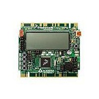
TWR-S08LH64 Freescale Semiconductor, TWR-S08LH64 Datasheet
TWR-S08LH64
Specifications of TWR-S08LH64


Related parts for TWR-S08LH64


TWR-S08LH64 Summary of contents
Page 1
... Demonstration Board for Freescale MC9S08LL and TWR-S08 MC9S08LH Families of Microcontrollers USER GUIDE www.axman.com Web Site: support@axman.com Support: ...
Page 2
CAUTIONARY NOTES .............................................................................................................. 4 TERMINOLOGY ......................................................................................................................... 4 FEATURES ................................................................................................................................ 5 GETTING STARTED .................................................................................................................. 6 MEMORY MAP .......................................................................................................................... 6 SOFTWARE DEVELOPMENT ................................................................................................... 6 DEVELOPMENT SUPPORT ...................................................................................................... 6 OSBDM BOOTLOADER........................................................................................................ 7 BDM_PORT HEADER ...
Page 3
... March 23, 2010 April 1, 2010 April 27, 2010 FIGURES REVISION Rev A Initial Release B Updated board name to TWR-S08 thru-out Updated References section to correct document names and remove C Support CD. Updated Figures to show board reference designators D Removed References section. E Added Differential ADC input section. Updated document format F ...
Page 4
... EMC Information on the TWR-S08 board: a) This product as shipped from the factory with associated power supplies and cables, has been verified to meet with requirements of CE and the FCC as a CLASS A product. ...
Page 5
... The integrated Open-Source BDM, software tools, and examples provided with the development board make application development and debug quick and easy. signals are available on one or both edge connectors. For purposes of this document, the TWR-S08 is described without regard to the MCU installed. Exceptions will be clearly noted. ...
Page 6
... PC to disconnect the board. Damage to the host PC, target board, or Tower System may result if this current limit is violated. The OSBDM will not connect to the TWR-S08 board if the target MCU is in STOP mode. Wake the target device with an external event then connect to ...
Page 7
When powered from the USB bus, do not exceed the 500mA maximum allowable current drain. Damage to the target board or host PC may result OSBDM Bootloader The OSBDM is pre-programmed ...
Page 8
... The external BDM is now ready for use. POWER The TWR-S08 board may be powered from the OSBDM or from the Tower System. 190mAH battery holder is applied for battery-powered operation. The USB current limit must be observed while using the USB connection from the host PC to supply power to the target board ...
Page 9
Figure 2: V_SEL Option Header, JP8 VR1 Enables voltage ...
Page 10
... Consult the target device RM for details on LVD operation. TIMING The TWR-S08 uses the MC9S08LL or MC9S08LH internal timing source by default. external 32 kHz XTAL oscillator, configured for low-power operation, is also provided. Consult the target device RM for details on configuring the selected timing source. ...
Page 11
... COM USB LCD The TWR-S08 applies a GD-5306P, 2x28 chip-on-glass, LCD connected directly to the target MCU. The target MCU provides the internal charge-pump and regulated LCD reference voltage required by the LCD. LCD contrast is trimmable under MCU control. Refer to the target device RM for further details on configuring using the LCD interface. The GD-5306P datasheet may be found on the Support CD included with the board ...
Page 12
... ACCELEROMETER The TWR-S08 applies the MMA7361L, 3-axis, analog accelerometer for tilt and motion-sense applications. The accelerometer supports 2 user selectable sensitivities - 1.5g / 6g. The SLEEP* input allows the device to be placed in a low-power mode. Separate X-, Y-, and Z- axis readings are routed to the MCU. Output filtering is applied to remove fast transients. ...
Page 13
... SW 1 may not function properly. Pushbutton Switches The TWR-S08 applies 4, normally open, push-button switches for user input. Each push- button switch is configured for active-low operation. A 22pF capacitor is applied to each push- button switch to minimize switch bounce. An external pull-up is applied to SW4 for use as and IRQ* input ...
Page 14
... JP11 (*) – Default Position Potentiometer The TWR-S08 board provides a 5K ohm potentiometer (POT) to simulate analog input. The POT is decoupled to minimize noise during adjustment. Figure 12 below shows the USER enable position and associated signal for the buzzer. Figure 12: POT Enable Option Header, JP12 ...
Page 15
... Differential ADC Input The TWR-S08LH64 board provides a differential ADC input to the MC9S08LH64. Option header JP10 allows the user to route the output and feedback from the Light Sensor (RZ1) to the MC9S08LH64 differential ADC input. To use this feature correctly, the user should remove the RZ1 jumper at JP7 ...
Page 16
PTC6/ACMPO/BKGD/MS PTC7/IRQ/TCLK PTC4/TPM1CH0 PTC5/TPM2CH1 3.3V Power PTA1/SPSCK/KBIP1/ADP5 PTA2/MISO/SDA/KBIP2/ADP6 PTA3/MOSI/SDA/KBIP3/ADP7 PTA4/KBIP4/ADP8/LCD43 ...
Page 17
PTC7/IRQ/TCLK 3.3V Power Figure 15: Secondary Edge Connector, J2 5.0V Power 3.3V Power Elevator Power Sense PTB4/MISO/SDA PTB5/MOSI/SCL PTB6/RXD2/SPSCK Pri_B61 Pri_A61 Pri_B62 Pri_A62 Pri_B63 Pri_A63 Pri_B64 Pri_A64 Ground Pri_B65 Pri_A65 Pri_B66 ...
Page 18
PTA4/KBIP4/ADP8/LCD43 PTA5/KBIP5/ADP9/LCD42 3.3V Power PTE6/LCD19 PTE4/LCD17 Sec_B24 Sec_A24 Sec_B25 Sec_A25 ...
Page 19
PTD5/LDC5 PTD3/LCD3 PTD1/LCD1 3.3V Power Sec_B74 Sec_A74 Sec_B75 Sec_A75 Sec_B76 ...