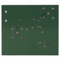
ZXFV202N8EV Diodes Zetex, ZXFV202N8EV Datasheet - Page 4

ZXFV202N8EV
Manufacturer Part Number
ZXFV202N8EV
Description
BOARD EVALUATION FOR ZXFV202
Manufacturer
Diodes Zetex
Specifications of ZXFV202N8EV
Main Purpose
Video, Amplifier, Single
Embedded
No
Utilized Ic / Part
ZXFV202
Primary Attributes
Current Feedback, 210MHz, 600V/us, ±5 V
Secondary Attributes
Gain of 1 or 2, 40mA Output
Lead Free Status / RoHS Status
Contains lead / RoHS non-compliant
ZXFV201, ZXFV202, ZXFV203, ZXFV204
Applications information
A typical circuit application is shown in Figure 1. This is suitable for 75
transmission line
connections at both the input and the output and is useful for distribution of wide-band signals
such as video via cables. The 75
reverse terminating resistor R4 gives the correct matching
condition to a terminated video cable. The amplifier load is then 150
in parallel with the local
feedback network.
470
470
Figure 1 Typical video signal application circuit, gain = 2 (overall gain = 1 for 75
load
The wide bandwidth of this device necessitates some care in the layout of the printed circuit. A
continuous ground plane is required under the device and its signal connection paths, to provide
the shortest possible ground return paths for signals and power supply filtering. A double-sided
or multi-layer PCB construction is required, with plated-through via holes providing closely
spaced low-inductance connections from some components to the continuous ground plane.
For the power supply filtering, low inductance surface mount capacitors are normally required. It
has been found that very good RF decoupling is provided on each supply using a 1000pF NPO
size 0805 or smaller ceramic surface mount capacitor, closest to the device pin, with an adjacent
0.1 F X7R capacitor. Other configurations are possible and it may be found that a single 0.01 F
X7R capacitor on each supply gives good results. However this should be supported by larger
decoupling capacitors elsewhere on the printed circuit board. Values of 1 to 10 F are
recommended, particularly where the voltage regulators are located more than a few inches from
the device. These larger capacitors are recommended to be solid tantalum electrolytic or ceramic
types.
Note particularly that the inverting input of this current feedback type of amplifier is sensitive to
small amounts of capacitance to ground which occur as part of the practical circuit board layout.
This capacitance affects bandwidth, frequency response peaking and pulse overshoot. Therefore
to minimize this capacitance, the feedback components R2 and R3 of Figure 1 should be
positioned as close as possible to the inverting input connection.
Issue 5 - May 2007
4
www.zetex.com
© Zetex Semiconductors plc 2007


