PS051 Microchip Technology, PS051 Datasheet - Page 2
PS051
Manufacturer Part Number
PS051
Description
BOARD POWER INFO FOR PS70X
Manufacturer
Microchip Technology
Datasheet
1.PS051.pdf
(8 pages)
Specifications of PS051
Processor To Be Evaluated
PS70X
Interface Type
RS-232, USB
Lead Free Status / RoHS Status
Request inventory verification / Request inventory verification
Lead Free Status / RoHS Status
Lead free / RoHS Compliant, Request inventory verification / Request inventory verification


PS051
1.0
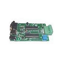
The PowerInfo 2 board is a simple, easy to use hard-
ware interface that supports configuration, verification
and test of Microchip PS70X and PS5XX ICs. It operates
under the control of Microchip’s development/test
software interfaced to a Windows PC.
The PowerInfo 2 board facilitates serial or USB com-
munication between the PC and the SMBus battery
interface. If connected to the PC’s serial (RS-232) port,
the PowerInfo 2 board must be powered through an
external 12V DC power supply. If connected through a
USB port, no additional power is required.
2.0
The Microchip PowerInfo 2 interface facilitates commu-
nication between a battery containing a Microchip
PS5XX or PS70X IC and a PC running Microchip’s
development/test software. The information that
follows will guide you through the setup of the various
features available.
2.1
• P1 – Serial (RS-232)
• J1 – USB
• J2 – 12V DC power supply (used with serial
• TB1 – Pluggable terminal block for device under
• TB2 – External charger or load connection
2.2
• ADR – Jumper for board address identification
DS21815C-page 2
Legend: O = open, X = connect
connection only)
test. Looking into the connector on the board, the
pins from left to right are:
- V+ (VP): Battery pack positive
- C: SMBus clock
- D: SMBus data
- T: T-pin
- V- (VN): Battery pack negative
Address
0
1
2
3
PRODUCT OVERVIEW
GENERAL SETUP
Connections
Jumpers
2-3
O
O
X
X
Jumper Position
1-4
X
O
X
O
2.3
The preferred method to connect PowerInfo 2 to the PC
is through the USB port. Connect the USB cable from
J1 on the PowerInfo 2 board to the USB port on the PC.
The board is now powered through the USB connec-
tion. Attach your battery to the TB1 connector and
launch the Microchip development/test software on the
PC.
2.4
Connect the serial cable from P1 on the PowerInfo 2
board to the RS-232 port on the PC. Connect a 12V DC
power supply to J2 and plug it into the electrical outlet.
The board is now powered. Attach your battery to the
TB1 connector and launch the Microchip development/
test software on the PC.
2.5
A battery charger or a load can be attached at TB2 to
exercise the device under test.
3.0
The software driver for PS700 was developed for a
PIC
PowerInfo 2 board when using a PS705X module
board or a PS7070 evaluation board. This software
driver is distributed on a PIC16F876 when a license
agreement has been executed.
3.1
Disconnect the PS051 from power and PC. Remove
the PIC microcontroller at location U1. Keep this IC in
a safe place as it must be replaced to operate the
PS051 with another PowerSmart
PS501. Install the PS700Driver at location U1. The
PowerInfo 2 board can now be used with the PS700
development products.
3.2
To use the PS051 with another PowerSmart product,
such as PS501, the PS700Driver must be removed and
the PIC microcontroller originally located at U1
replaced. Disconnect the PS051 from power and PC.
Remove the PS700Driver at location U1. Install the
original PIC microcontroller and reconnect PC and
power connections.
®
microcontroller and can be installed on the
USB Setup
RS-232 Setup
Charger/Load Setup (Optional)
PS700Driver SETUP
Installing PS700Driver
Removing PS700Driver
2004 Microchip Technology Inc.
®
product, such as
Related parts for PS051
Image
Part Number
Description
Manufacturer
Datasheet
Request
R

Part Number:
Description:
Manufacturer:
Microchip Technology Inc.
Datasheet:
Part Number:
Description:
Manufacturer:
Microchip Technology Inc.
Datasheet:
Part Number:
Description:
Manufacturer:
Microchip Technology Inc.
Datasheet:
Part Number:
Description:
Manufacturer:
Microchip Technology Inc.
Datasheet:
Part Number:
Description:
Manufacturer:
Microchip Technology Inc.
Datasheet:
Part Number:
Description:
Manufacturer:
Microchip Technology Inc.
Datasheet:
Part Number:
Description:
Manufacturer:
Microchip Technology Inc.
Datasheet:
Part Number:
Description:
Manufacturer:
Microchip Technology Inc.
Datasheet: