AD9956/PCB Analog Devices Inc, AD9956/PCB Datasheet - Page 17
AD9956/PCB
Manufacturer Part Number
AD9956/PCB
Description
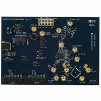
BOARD EVAL FOR AD9956
Manufacturer
Analog Devices Inc
Datasheet
1.AD9956YCPZ.pdf
(32 pages)
Specifications of AD9956/PCB
Module/board Type
Evaluation Board
For Use With/related Products
AD9956
Lead Free Status / RoHS Status
Contains lead / RoHS non-compliant


APPLICATION CIRCUIT EXPLANATIONS
Dual-Clock Configuration
In this loop, M = 1, N = 16, and R = 4. The DDS tuning word is
also equal to ¼ so that the frequency of CLOCK 1’ equals the
frequency of CLOCK 1. Phase adjustments in the DDS provide
a 14-bit programmable rising edge skew capability of CLOCK 1’
with respect to CLOCK 1 (see Figure 22).
Fractional-Divider Loop
This loop offers the precise frequency division (48-bit) of the
DDS in the feedback path as well as the frequency sweeping
capability of the DDS. Programming the DDS to sweep from
24 MHz to 25 MHz sweeps the output of the VCO from
2.7 GHz to 2.6 GHz. The reference in this case is a simple
crystal (see Figure 23).
REFERENCE
EXTERNAL
DDS
÷M
÷N
DAC
PHASE FREQUENCY
AD9956
DETECTOR
REF
OSC
Figure 25. Optical Networking Clock
LPF
Figure 26. Direct Upconversion
÷N
CHARGE
PUMP
Rev. A | Page 17 of 32
FREQUENCY
DETECTOR
PLLREF
PLLOSC
PHASE
DDS
LPF
÷R
LO and Baseband Modulation Generation
Using the AD9956’s PLL section to generate an LO and the
DDS portion to generate a modulated baseband, this circuit
uses an external mixer to perform some simple modulation at
RF frequencies (see Figure 24).
Optical Networking Clock
This is the AD9956 configured as an optical networking clock.
The loop can be used to generate a 622 MHz clock for OC12.
The DDS can be programmed to output 8 kHz to serve as a base
reference for other circuits in the subsystem (see Figure 25).
Direct Upconversion
The AD9956 is configured to use the DDS as a precision refer-
ence to the PLL loop. Since the VCO is < 655 MHz, it can be fed
straight into the phase frequency detector feedback input (with
the divider enabled), as seen in Figure 26.
CHARGE
PUMP
622MHz
DAC
VCO
DRIVER
LPF
CML
VCO
≤650MHz
CLOCK1
CLOCK2
AD9956
Related parts for AD9956/PCB
Image
Part Number
Description
Manufacturer
Datasheet
Request
R

Part Number:
Description:
400 Msps 14 Bit DDS EvBd. W/2450MHz VCO
Manufacturer:
Analog Devices Inc
Datasheet:
Part Number:
Description:
400 Msps 14 Bit DDS Eval Bd.
Manufacturer:
Analog Devices Inc
Datasheet:
Part Number:
Description:
BOARD EVAL 14BIT 1.8V 48LFCSP
Manufacturer:
Analog Devices Inc
Datasheet:


Part Number:
Description:
±1.7g Dual-Axis IMEMS Accelerometer Evaluation Board
Manufacturer:
Analog Devices Inc
Datasheet:
Part Number:
Description:
Inertial Sensor Evaluation System
Manufacturer:
Analog Devices Inc
Datasheet:
Part Number:
Description:
Manufacturer:
Analog Devices Inc
Datasheet:
Part Number:
Description:
Manufacturer:
Analog Devices Inc
Datasheet:
Part Number:
Description:
Manufacturer:
Analog Devices Inc
Datasheet:
Part Number:
Description:
Manufacturer:
Analog Devices Inc
Datasheet:
Part Number:
Description:
Manufacturer:
Analog Devices Inc
Datasheet:
Part Number:
Description:
Manufacturer:
Analog Devices Inc
Datasheet:
Part Number:
Description:
Manufacturer:
Analog Devices Inc
Datasheet: