ADNB-7052-EV Avago Technologies US Inc., ADNB-7052-EV Datasheet - Page 17
ADNB-7052-EV
Manufacturer Part Number
ADNB-7052-EV
Description
OPTICAL MOUSE EVALUATION KIT
Manufacturer
Avago Technologies US Inc.
Series
LaserStream™r
Type
Optical Mouser
Datasheet
1.ADNB-7052-EV.pdf
(45 pages)
Specifications of ADNB-7052-EV
Contents
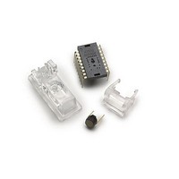
Mouse Sensor, VCSEL, Lens, Laser Assembly Clip and Documentation
Description/function
Laser Mouse Bundle
Interface Type
SPI
Product
Display Modules
Touch Panel
No Touch Panel
For Use With/related Products
ADNS-7050
Lead Free Status / Rohs Status
Details
Other names
Q2656643
Q2755626
Q2755626


serial communication and put the chip into an unknown
state. In addition, NCS must be raised after each burst-
mode transaction is complete to terminate burst-mode.
The port is not available for further use until burst-mode
is terminated.
Write Operation
Write operation, defined as data going from the micro-
controller to the ADNS-7050, is always initiated by the
micro-controller and consists of two bytes. The first byte
contains the address (seven bits) and has a “1” as its MSB
to indicate data direction. The second byte contains
the data. The ADNS-7050 reads MOSI on rising edges of
SCLK.
NCS
SCLK
CYCLE #
SCLK
MOSI
MISO
Figure 16. Read operation.
SCLK
17
t
Figure 17. MISO delay and hold time.
Note:
The 0.5/fSCLK minimums high state of SCLK is also the minimum MISO
data hold time of the ADNS-7050. Since the falling edge of SCLK is ac-
tually the start of the next read or write command, the ADNS-7050 will
hold the state of data on MISO until the falling edge of SCLK.
Figure 18. Timing between two write commands.
DLY-MISO
SCLK
MISO
ADDRESS
1
1
WRITE OPERATION
D
t
0
HOLD-MISO
2
A 6
3
A 5
DATA
4
A 4
5
A 3
6
A 2
t SRAD DELAY
7
A 1
ADDRESS
A 0
8
Required Timing Between Read and Write Commands
There are minimum timing requirements between read
and write commands on the serial port.
Read Operation
A read operation, defined as data going from the ADNS-
7050 to the micro-controller, is always initiated by the
micro-controller and consists of two bytes. The first byte
contains the address, is sent by the micro-controller over
MOSI, and has a “0” as its MSB to indicate data direction.
The second byte contains the data and is driven by the
ADNS-7050 over MISO. The sensor outputs MISO bits on
falling edges of SCLK and samples MOSI bits on every ris-
ing edge of SCLK.
t
SWW
WRITE OPERATION
9
D 7
10
D 6
DATA
11
D 5
12
D 4
13
D 3
14
D 2
15
D 1
16
D 0
Related parts for ADNB-7052-EV
Image
Part Number
Description
Manufacturer
Datasheet
Request
R

Part Number:
Description:
Display Modules & Development Tools Bundle w/Trim Lens
Manufacturer:
Avago Technologies US Inc.

Part Number:
Description:
Display Modules & Development Tools Bundle w/Trim Lens
Manufacturer:
Avago Technologies US Inc.

Part Number:
Description:
Display Modules & Development Tools Mouse sensor
Manufacturer:
Avago Technologies US Inc.
Part Number:
Description:
Display Modules & Development Tools Mouse sensor
Manufacturer:
Avago Technologies US Inc.

Part Number:
Description:
Display Modules & Development Tools Bundle w/Trim Lens
Manufacturer:
Avago Technologies US Inc.

Part Number:
Description:
Display Modules & Development Tools Sensor+Round Lens
Manufacturer:
Avago Technologies US Inc.
Part Number:
Description:
Display Modules & Development Tools Mouse sensor
Manufacturer:
Avago Technologies US Inc.

Part Number:
Description:
Display Modules & Development Tools Mouse sensor
Manufacturer:
Avago Technologies US Inc.

Part Number:
Description:
Display Modules & Development Tools Bundle w/Trim Lens
Manufacturer:
Avago Technologies US Inc.
Part Number:
Description:
Display Modules & Development Tools Mouse sensor
Manufacturer:
Avago Technologies US Inc.

Part Number:
Description:
OPTOCOUPLER GATE DRV 2A 16-SOIC
Manufacturer:
Avago Technologies US Inc.
Datasheet:
Part Number:
Description:
OPTOCOUPLER 2CH 2.5A 16-SOIC
Manufacturer:
Avago Technologies US Inc.
Datasheet:

Part Number:
Description:
OPTOCOUPLER GATE DRV 0.4A 16SOIC
Manufacturer:
Avago Technologies US Inc.
Datasheet:

Part Number:
Description:
OPTOCOUPLER 2.0A 250KHZ 8-DIP
Manufacturer:
Avago Technologies US Inc.
Datasheet:

Part Number:
Description:
OPTOCOUPLER 2.0A 250KHZ GW 8-SMD
Manufacturer:
Avago Technologies US Inc.
Datasheet: