DSP1A-DC24V Panasonic Electric Works, DSP1A-DC24V Datasheet - Page 3
DSP1A-DC24V
Manufacturer Part Number
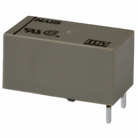
DSP1A-DC24V
Description
RELAY MINI SPST 8A 24VDC PC MNT
Manufacturer
Panasonic Electric Works
Series
DSPr
Type
Power Relayr
Specifications of DSP1A-DC24V
Relay Type
General Purpose
Contact Form
SPST-NO (1 Form A)
Contact Rating (current)
8A
Switching Voltage
250VAC
Coil Type
Standard
Coil Current
12.5mA
Coil Voltage
24VDC
Turn On Voltage (max)
19.2 VDC
Turn Off Voltage (min)
2.4 VDC
Mounting Type
Through Hole
Termination Style
PC Pin
Circuit
SPST-NO (1 Form A)
Contact Rating @ Voltage
8A @ 250VAC
Control On Voltage (max)
19.2 VDC
Control Off Voltage (min)
2.4 VDC
Brand/series
DS-P Series
Current, Rating
8⁄5 AAC⁄ADC
Dielectric Rating
1000 V (RMS) (Initial, Between Open Contacts), 3000 V (RMS) (Initial, Between Contacts and Coil)
Dimensions
0.795 in. L x 0.413 in. H x 0.433 in. D
Function
Power
Latch Type
Single Side Stable
Material, Contact
Gold Flash Over Silver Alloy
Number Of Pins
4
Standards
UL, CSA, TUV
Temperature, Operating, Maximum
65 °C
Temperature, Operating, Minimum
-40 °C
Termination
Solder
Voltage, Control
24 VDC
Voltage, Rating
380 VAC
Relay Construction
Non-Latching
Contact Arrangement
SPST-NO
Coil Voltage Dc
24V
Voltage Rating (vdc)
30V
Voltage Rating (vac)
250V
Dropout Volt (min)
2.4VDCV
Coil Resistance
1.92kohm
Pick-up Voltage (max)
19.2VDC
Maximum Power Rating
150W/2KVA
Operate Time
10ms
Contact Current Rating
5DC/8ACA
Contact Material
Silver Tin Oxide/Gold Flash
Coil Suppression Diode
No
Push To Test Button
No
Led Indicator
No
Seal
Sealed
Product Height (mm)
10.5mm
Product Depth (mm)
11mm
Product Length (mm)
20.2mm
Operating Temp Range
-40C to 60C
Pin Count
4
Mounting Style
Through Hole
Lead Free Status / RoHS Status
Lead free / RoHS non-compliant
Other names
255-1051
DSP1AE-DC24V
DSP1AE-DC24V
Available stocks
Company
Part Number
Manufacturer
Quantity
Price
Company:

Part Number:
DSP1A-DC24V
Manufacturer:
NAIS/PANASONIC
Quantity:
20 000


2. Specifications
Notes: *1. This value can change due to the switching frequency, environmental conditions, and desired reliability level, therefore it is recommended to check this with the
REFERENCE DATA
1. Max. switching capacity
3.-(1) Coil temperature rise (1 Form A)
Tested sample: DSP1a-DC12V, 5 pcs.
Contact
Rating
Electrical
characteristics
Mechanical
characteristics
Expected life
Conditions
Unit weight
Characteristics
0.1
60
50
40
30
20
10
10
1
*2. Wave is standard shock voltage of 1.2 50 s according to JEC-212-1981
*3. The upper limit of the ambient temperature is the maximum temperature that can satisfy the coil temperature rise value. Refer to Usage, transport and storage
0
10
DC resistive
load (1a)
DC resistive load
(1a1b,2a)
actual load.
conditions in NOTES.
80
Coil applied voltage, %V
Arrangement
Contact resistance (Initial)
Contact material
Nominal switching capacity (resistive load)
Max. switching power (resistive load)
Max. switching voltage
Max. switching current
Nominal operating power
Min. switching capacity (Reference value)*
Insulation resistance (Initial)
Breakdown voltage
(Initial)
Surge breakdown
voltage*
Temperature rise (coil) (at 65 C
Operate time [Set time] (at 20 C
Release time [Reset time] (at 20 C
Shock resistance
Vibration resistance
Mechanical
Electrical
Conditions for operation, transport and storage*
(Not freezing and condensing at low temperature)
Solder heating
Max. operating speed
Contact voltage, V
AC resistive
(1a1b,2a)
100
100
load
2
AC resistive
load (1a)
120
8A
0A
All Rights Reserved © COPYRIGHT Panasonic Electric Works Co., Ltd.
1000
Between open contacts
Between contact sets
Between contact and coil
between contacts and coil
Functional
Destructive
Functional
Destructive
Item
149
68
68
2.-(1) Life curve (1 Form A 1 Form B)
3.-(2) Coil temperature rise
(1 Form A 1 Form B)
Tested sample: DSP1-DC12V, 5 pcs.
F)
F)
F)
100
10
1
60
50
40
30
20
10
0
0
265 V·130 V AC
3
cos = 0.4
1
80
2
Min. 1,000M (at 500V DC) Measurement at same location as “Breakdown voltage” section.
Max. 10 ms [10 ms] (Nominal coil voltage applied to the coil, excluding contact bounce time.)
Max. 5 ms [10 ms] (Nominal coil voltage applied to the coil, excluding contact bounce time.)
8 A 250 V AC, 5A 30V DC
Coil applied voltage, %V
Switching capacity, A
Ambient temperature:
3
265 V·130 V AC cos = 1
2,000 VA, 150 W
–40 F to +140 F
–40 C to +60 C
8 A AC, 5 A DC
100
Min. 196 m/s
Max. 55 C
1 Form A
4
2,000 Vrms (1 Form A 1 Form B, 2 Form A) (Detection current: 10mA.)
10 to 55 Hz at double amplitude of 2 mm (Detection time: 10 s.)
5
250 C
Min. 980 m/s
120
6
2
1,000 Vrms for 1min. (Detection current: 10mA.)
3,000 Vrms for 1min. (Detection current: 10mA.)
(Half-wave pulse of sine wave: 11 ms; detection time: 10 s.)
5A
0A
10 to 55 Hz at double amplitude of 3.5 mm
482 F
Max. 30 m (By voltage drop 6 V DC 1A)
7
(Soldering depth: 2/3 terminal pitch)
Min. 5 10
(10s), 300 C
2
Au-flashed AgSnO
Min. 10
(Half-wave pulse of sine wave: 6 ms.)
Ambient temperature:
380 V AC, 125 V DC
Approx. 4.5 g
1 Form A 1 Form B
–40 F to +149 F
–40 C to +65 C
(without diode)
10m A 5 V DC
Specifications
2.-(2) Life curve (1 Form A 1 Form B)
3.-(3) Coil temperature rise (2 Form A)
Tested sample: DSP2a-DC12V, 5 pcs.
Max. 40 C
7
5
300 mW
5,000 V
(at 180 times/min.)
(resistive load)
3 cps
100
572 F
50
10
60
50
40
30
20
10
0
5 A 250 V AC, 5 A 30 V DC
.16 oz
(5s), 350 C
2
30 V DC L/R = 7 ms
1,250 VA, 150 W
type
80
5 A AC, DC
0.5
Coil applied voltage, %V
Switching capacity, A
662 F
Ambient temperature:
100
1
–40 F to +140 F
–40 C to +60 C
(3s)
Max. 55 C
2 Form A
30 V DC resistive
5
120
5A
0A
DSP
10
Related parts for DSP1A-DC24V
Image
Part Number
Description
Manufacturer
Datasheet
Request
R

Part Number:
Description:
RELAY MINI SPST 8A 5VDC PC MNT
Manufacturer:
Panasonic Electric Works
Datasheet:
Part Number:
Description:
RELAY MINI SPST 8A 12VDC PC MNT
Manufacturer:
Panasonic Electric Works
Datasheet:

Part Number:
Description:
RELAY MINI POWER 9VDC PCB
Manufacturer:
Panasonic Electric Works
Datasheet:

Part Number:
Description:
RELAY MINI PWR 2-LATCH 6VDC PCB
Manufacturer:
Panasonic Electric Works
Datasheet:
Part Number:
Description:
RELAY MINI PWR 2-LATCH 9VDC PCB
Manufacturer:
Panasonic Electric Works
Datasheet:

Part Number:
Description:
SOCKET PC MNT FOR DSP1A-L2 RELAY
Manufacturer:
Panasonic Electric Works
Datasheet:

Part Number:
Description:
SOCKET PC MNT FOR DSP1A RELAYS
Manufacturer:
Panasonic Electric Works
Datasheet:
Part Number:
Description:
RELAY MINI 8A 5VDC PCB
Manufacturer:
Panasonic Electric Works
Datasheet:
Part Number:
Description:
RELAY MINI POWER 24VDC PCB
Manufacturer:
Panasonic Electric Works
Datasheet:
Part Number:
Description:
RELAY MINI POWER 3VDC PCB
Manufacturer:
Panasonic Electric Works
Datasheet:

Part Number:
Description:
CONN SOCKET P4 .4MM 50POS SMD
Manufacturer:
Panasonic Electric Works
Datasheet:
Part Number:
Description:
CONN SOCKET .8MM 16POS SMD
Manufacturer:
Panasonic Electric Works
Datasheet:
Part Number:
Description:
CONN HEADER .8MM 16POS SMD
Manufacturer:
Panasonic Electric Works
Datasheet:
Part Number:
Description:
CONN SOCKET .8MM 20POS SMD
Manufacturer:
Panasonic Electric Works
Datasheet:
Part Number:
Description:
CONN SOCKET .8MM 20POS SMD
Manufacturer:
Panasonic Electric Works
Datasheet: