GN (AGN)
SPECIFICATIONS
Contact
Remarks:
* Specifications will vary with foreign standards certification ratings.
*
*
*
*
*
*
*
*
Arrangement
Initial contact resistance, max.
(By voltage drop 6 V DC 1A )
Contact material
Rating
Nominal
operating
power
Expected
life (min.
operations)
1
2
3
4
5
6
7
8
10.60 0.3
.417 .012
Measurement at same location as “Initial breakdown voltage” section.
Detection current: 10mA.
Nominal voltage applied to the coil, excluding contact bounce time.
By resistive method, nominal voltage applied to the coil; contact carrying current:
1 A.
Half-wave pulse of sine wave: 6 ms; detection time: 10 s.
Half-wave pulse of sine wave: 6 ms.
Detection time: 10 s.
Refer to 6. Conditions for operation, transport and storage mentioned in
AMBIENT ENVIRONMENT
Nominal switching capacity
(resistive load)
Max. switching power
(resistive load)
Max. switching voltage
Max. switching current
Min. switching capacity
Single side stable
1 coil latching
Mechanical (at 180 cpm)
Electrical
(at 20 cpm)
9.00 0.3
.354 .012
5.70 0.3
.224 .012
10.60 0.3
.417 .012
1 A 30 V DC
resistive
0.3 A 125 V AC
resistive
Max.10.00
5.70 0.3
.224 .012
mm
1
.394
inch
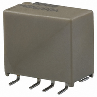
ULTRA-SMALL PACKAGE
SLIM POLARIZED RELAY
Stationary: AgPd+Au clad
140mW (1.5 to 12 V DC)
100mW (1.5 to 12 V DC)
110 V DC, 125 V AC
230mW (24 V DC)
120mW (24 V DC)
10 A 10 mV DC
Movable: AgPd
0.3 A 125 V AC
30 W, 37.5 V A
FEATURES
• Compact slim body saves space
Thanks to the small surface area of 5.7
mm
low height of 9.0 mm
packaging density can be increased to
allow for much smaller designs.
• Outstanding surge resistance.
Surge withstand between open contacts:
1,500 V 10 160 s (FCC part 68)
Surge withstand between contacts and
coil: 2,500 V 2 10 s (Telcordia)
• The use of twin crossbar contacts
ensures high contact reliability.
AgPd contact is used because of its good
sulfide resistance. Adopting low-gas
molding material. Coil assembly molding
technology which avoids generating
volatile gas from coil.
1 A 30 V DC
2 Form C
100 m
5
1 A
10
10
10.6 mm
10
5
5
7
.224 inch
.354
Characteristics
Notes:
Initial insulation resistance*
Initial
breakdown
voltage*
Initial surge
voltage
Operate time [Set time]*
Release time (without diode)
[Reset time]*
Temperature rise*
Shock resistance
Vibration resistance
Conditions for
operation, transport
and storage*
(Not freezing and
condensing at low
temperature)
Unit weight
1 This value can change due to the switching frequency, environmental conditions,
2 The upper limit for the ambient temperature is the maximum temperature that
and desired reliability level, therefore it is recommended to check this with the
actual load.
can satisfy the coil temperature rise. Under the packing condition, allowable
temperature range is from –40 to +70 C
inch, the
.417 inch
2
8
3
Between open contacts
Between contact sets
Between contacts and coil
Between open contacts
(10 160 s)
Between contacts and coil
(2 10 s)
(at 20 C)
and
4
(at 20 C)
GN RELAYS
3
Functional*
Destructive*
Functional*
Destructive
Ambient
temperature
Humidity
• Increased packaging density
Due to highly efficient magnetic circuit
design, leakage flux is reduced and
changes in electrical characteristics from
components being mounted close-
together are minimized. This all means a
packaging density higher than ever
before.
• Nominal operating power: 140 mW
• Outstanding vibration and shock
resistance.
Functional shock resistance:
750 m/s
Destructive shock resistance:
1,000 m/s
Functional vibration resistance:
10 to 55 Hz (at double amplitude of 3.3
mm
Destructive vibration resistance:
10 to 55 Hz (at double amplitude of 5 mm
.197
(at 20 C)
1
.130
inch)
(AGN)
2
{75G}
inch)
5
7
2
6
{100G}
–40 to +158
2
Min. 1,000M
[Max. 4 ms (Approx. 2 ms)]
[Max. 4 ms (Approx. 2 ms)]
Max. 4 ms (Approx. 2 ms)
Max. 4 ms (Approx. 1 ms)
1,500 V (FCC Part 68)
Min. 1,000 m/s
10 to 55 Hz at double
10 to 55 Hz at double
1,000 Vrms for 1min.
1,500 Vrms for 1min.
amplitude of 3.3 mm
Approx. 1 g
Min. 750 m/s
750 Vrms for 1min.
2,500 V (Telcordia)
amplitude of 5 mm
–40 F to 185 F
–40 C to 85 C
5 to 85% R.H.
F.
Max. 50 C
(at 500V DC)
.035 oz
2
2
{75G]
{100G]
TESTING