HC1-PS-K Panasonic Electric Works, HC1-PS-K Datasheet - Page 8
HC1-PS-K
Manufacturer Part Number
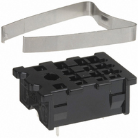
HC1-PS-K
Description
SOCKET PCB W/CLIP FOR HC1 RELAYS
Manufacturer
Panasonic Electric Works
Series
HCr
Type
Socketr
Datasheet
1.HC-BRACKET.pdf
(8 pages)
Specifications of HC1-PS-K
Number Of Positions
5
Mounting Type
Through Hole
Termination Style
PC Pin
Features
Mounting Hardware
For Use With/related Products
HC1 Relays
For Use With
HC1-HL-DC6V-F - RELAY PWR 10A SPDT 6VDC LEDHC1-HL-DC48V-F - RELAY PWR 10A SPDT 48VDC LEDHC1-HL-DC24V-F - RELAY PWR 10A SPDT 24VDC LEDHC1-HL-DC12V-F - RELAY PWR 10A SPDT 12VDC LEDHC1-HL-DC100V-F - RELAY PWR 10A SPDT 100VDC LEDHC1-HL-AC6V-F - RELAY PWR 10A SPDT 6VAC LEDHC1-HL-AC48V-F - RELAY PWR 10A SPDT 48VAC LEDHC1-HL-AC24V-F - RELAY PWR 10A SPDT 24VAC LEDHC1-HL-AC240V-F - RELAY PWR 10A SPDT 240VAC LEDHC1-HL-AC12V-F - RELAY PWR 10A SPDT 12VAC LEDHC1-HL-AC120V-F - RELAY PWR 10A SPDT 120VAC LEDHC1-H-DC6V-F - RELAY PWR 10A SPDT 6VDC PLUGINHC1-H-DC48V-F - RELAY PWR 10A SPDT 48VDC PLUGINHC1-H-DC100V-F - RELAY PWR 10A SPDT 100VDC PLUGINHC1-H-AC6V-F - RELAY PWR 10A SPDT 6VAC PLUGINHC1-H-AC48V-F - RELAY PWR 10A SPDT 48VAC PLUGINHC1-H-AC24V-F - RELAY PWR 10A SPDT 24VAC PLUGINHC1-H-AC12V-F - RELAY PWR 10A SPDT 12VAC PLUGINHC1-H-AC120V-F - RELAY PWR 10A SPDT 120VAC PLUGIN255-2747 - RELAY PWR 10A SPDT 240VAC PLUGINHC1-HL-AC100V-F - RELAY PWR SPDT 10A 100V PLUG-IN255-2749 - RELAY PWR SPDT 10A 24VDC PLUG-IN255-2748 - RELAY PWR SPDT 10A 12VDC PLUG-IN
Lead Free Status / RoHS Status
Lead free / RoHS Compliant
Other names
255-1941
HC1-PS-K
HC1-PS-K
Available stocks
Company
Part Number
Manufacturer
Quantity
Price
Company:

Part Number:
HC1-PS-K
Manufacturer:
Panasonic Electric Works
Quantity:
135


HC
3. TM type
Chassis (Panel) cutout
Schematic
Same schematic as plug-in type HC relay
Be aware that there is no LED indicator with CR
circuit and built-in diode types.
For Cautions for Use, see Relay Technical Information.
2-3.6 dia.
2-.142 dia.
1.480
37.6
Tolerance: 0.1
.004
4 Form C type External dimensions
.142
3.6
All Rights Reserved © COPYRIGHT Matsushita Electric Works, Ltd.
13
1
5
9
13.35
.526
4.45
.175
20.6
.811
10
2
6
Chassis (Panel) cutout in tandem mounting
Notes: 1. In mounting, use M3 screws and M3 washers.
11
3
7
4
8
12
14
4.31
.170
.039
2.54
.100
4.06
.160
6.35
.250
6.35
.250
1
34.2
1.346
6.4
.252
2. When mounting TM types, use washers to prevent damage or distortion to the polycarbonate cover.
3. When tightening fixing screws, the optimum torque range should be 0.294 to 0.49 N·m, (3 to 5 kgf·cm).
27
1.063
Moreover, use washers to prevent loosening.
.020
0.5
37.6
1.480
1.480
37.6
General tolerance: 0.3
1.693
43
.827
.079
21
2
.906
23
.827
21
2
.079
.012
The diagrams show the external dimensions of
the 4 Form C and 4-pole bifurcated (twin) types.
For 1 Form C, 2 Form C, and 3 Form C, see
diagrams at plug-in types (only the terminals are
different).
Related parts for HC1-PS-K
Image
Part Number
Description
Manufacturer
Datasheet
Request
R

Part Number:
Description:
RELAY PWR 10A SPDT SPDT 115VAC P
Manufacturer:
Panasonic Electric Works
Datasheet:

Part Number:
Description:
Relay Sockets & Hardware FOR HC1 RELAY SOLDER TAB
Manufacturer:
Panasonic
Datasheet:

Part Number:
Description:
SOCKET WRAP WIRE/CLIP HC1 RELAYS
Manufacturer:
Panasonic Electric Works
Datasheet:

Part Number:
Description:
Relay Sockets & Hardware 1 Form C 220/240V
Manufacturer:
Panasonic
Datasheet:
Part Number:
Description:
Relay Sockets & Hardware 1 Form C 240VAC PCB Type
Manufacturer:
Panasonic
Datasheet:
Part Number:
Description:
Relay Sockets & Hardware 1 Form C 12VDC PCB Type
Manufacturer:
Panasonic
Datasheet:
Part Number:
Description:
Relay Sockets & Hardware 1 Form C 6VDC Plug-In
Manufacturer:
Panasonic
Datasheet:
Part Number:
Description:
Relay Sockets & Hardware 1 Form C 24VAC Top Mount
Manufacturer:
Panasonic
Datasheet:
Part Number:
Description:
Relay Sockets & Hardware 1 Form C 115VAC Top Mount
Manufacturer:
Panasonic
Datasheet:
Part Number:
Description:
Relay Sockets & Hardware 1 Form C 115VAC PCB Type
Manufacturer:
Panasonic
Datasheet:

Part Number:
Description:
CONN SOCKET P4 .4MM 50POS SMD
Manufacturer:
Panasonic Electric Works
Datasheet:
Part Number:
Description:
CONN SOCKET .8MM 16POS SMD
Manufacturer:
Panasonic Electric Works
Datasheet:
Part Number:
Description:
CONN HEADER .8MM 16POS SMD
Manufacturer:
Panasonic Electric Works
Datasheet:
Part Number:
Description:
CONN SOCKET .8MM 20POS SMD
Manufacturer:
Panasonic Electric Works
Datasheet:
Part Number:
Description:
CONN SOCKET .8MM 20POS SMD
Manufacturer:
Panasonic Electric Works
Datasheet: