CPC1225NTR Clare, CPC1225NTR Datasheet
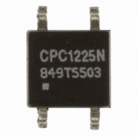
RELAY OPTOMOS SPST-NO 120MA 4SOP

CPC1225NTR

Manufacturer Part Number
CPC1225NTR
Description
RELAY OPTOMOS SPST-NO 120MA 4SOP
Manufacturer
Clare
Series
CPC, OptoMOS®r
Datasheet

Specifications of CPC1225NTR

Circuit
SPST-NO (1 Form A)
Output Type
AC, DC
On-state Resistance
30 Ohm
Load Current
120mA
Voltage - Input
1.2VDC
Voltage - Load
0 ~ 400 V
Mounting Type
Surface Mount
Termination Style
Gull Wing
Package / Case
4-SOP
Lead Free Status / RoHS Status
Lead free / RoHS Compliant
Other names
CLA312TR
DS-CPC1225N-R04
Features
Applications
Parameter
Blocking Voltage
Load Current
Max On-resistance
Pb
0.4mm Distance Through Insulation
(Supplementary Isolation Requirement of
EN60950)
1500V
Small 4-Pin SOP Package
Low Drive Power Requirements (TTL/CMOS
Compatible)
No Moving Parts
High Reliability
Arc-Free With No Snubbing Circuits
No EMI/RFI Generation
Machine Insertable, Wave Solderable
Tape & Reel Version Available
Telecommunications
Instrumentation
Medical Equipment-Patient/Equipment Isolation
Security
Aerospace
Industrial Controls
Telecom Switching
Tip/Ring Circuits
Modem Switching (Laptop, Notebook, Pocket
Size)
Hook Switch
Dial Pulsing
Ground Start
Ringing Injection
Multiplexers
Data Acquisition
Electronic Switching
I/O Subsystems
Meters (Watt-Hour, Water, Gas)
rms
2002/95/EC
RoHS
Input/Output Isolation
e
3
Rating
400
120
30
Units
mA
V
Ω
P
www.clare.com
Approvals
Pin Configuration
Description
Ordering Information
The CPC1225N is a miniature single-pole, normally
open (1-Form-A) solid state relay that employs
Clare’s patented, optically isolated OptoMOS
architecture to provide 1500V
isolation. A highly efficient GaAIAs infrared LED
controls the optically coupled output. The device
also complies with the Supplementary Isolation
requirements of EN/IEC 60950-1.
The CPC1225N uses Clare’s state of the art double
molded vertical construction to produce one of the
world’s smallest 4-pin relays. It offers board space
savings approaching 20% over the competitor’s
larger 4-pin SOP relay.
Part #
CPC1225N
CPC1225NTR
UL 1577 Approved Component: File E76270
CSA Certified Component: Certificate 1172007
EN 60950 Certified Component:
TUV Certificate B 10 05 49410 006
I
Form-A
I
of Normally Open Devices
LOAD
Switching Characteristics
F
– Control
4-Pin SOP OptoMOS
+ Control
Single-Pole, Normally Open
Description
4-Pin SOP (100/tube)
4-Pin SOP (2000/reel)
2
1
90%
t
on
rms
4
3
of input-to-output
Load
Load
CPC1225N
10%
t
off
®
Relay
1

Related parts for CPC1225NTR

CPC1225NTR Summary of contents

Page 1

... SOP relay. Approvals • UL 1577 Approved Component: File E76270 • CSA Certified Component: Certificate 1172007 • EN 60950 Certified Component: TUV Certificate 49410 006 Ordering Information Part # CPC1225N CPC1225NTR Pin Configuration + Control – Control Switching Characteristics of Normally Open Devices Form LOAD www.clare.com CPC1225N ® ...

Page 2

... rms °C °C Conditions Symbol - I L t=10ms I LPK I =120mA =400V LEAK =5mA, V =10V off V =50V, f=1MHz C L OUT I =120mA =5mA = I www.clare.com CPC1225N Min Typ Max Units - - 120 350 - 0.3 0. 0.9 1.2 1 Ω µ µA pF R04 ...

Page 3

... LED Forward Current (mA) Typical Turn-On vs. Temperature (I =80mA) L 1.8 1.6 I =2mA F 1.4 I =5mA 1.2 F 1.0 0.8 -40 - 100 Temperature (ºC) www.clare.com CPC1225N Typical On-Resistance Distribution (N=50, I =2mA, I =120mA, T =25º 17.5 18.0 18.5 19.0 19.5 20.0 20.5 On-Resistance (Ω) Typical Blocking Voltage Distribution (N=50, T =25º ...

Page 4

... Temperature (ºC) (V =400V) L 1.0 0.9 0.8 0.7 0.6 0.5 0.4 0.3 0.2 0 100 10μs 100μs Temperature (ºC) www.clare.com CPC1225N Typical On-Resistance vs. Temperature (I =10mA, I =80mA 100 -40 - Temperature (ºC) Typical Blocking Voltage vs. Temperature 460 450 440 430 420 410 400 390 ...

Page 5

... Clare recommends the use of no-clean flux formulations. However, board washing to remove flux residue is acceptable. Since Clare employs the use of silicone coating as an optical waveguide in many of its optically isolated products, the use of a short drying bake could be necessary if a wash is used after solder reflow processes. ...

Page 6

... The products described in this document are not designed, intended, authorized or warranted for use as components in systems intended for surgical implant into the body other applications intended to support or sustain life, or where malfunction of Clare’s product may result in direct physical harm, injury, or death to a person or severe property or environmental damage ...

Related keywords