PR26MF21NSZF Sharp Microelectronics, PR26MF21NSZF Datasheet
PR26MF21NSZF
Specifications of PR26MF21NSZF
Available stocks


Related parts for PR26MF21NSZF


PR26MF21NSZF Summary of contents
Page 1
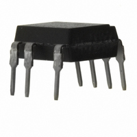
... Non-zero cross type is also available. (PR26MF1xNSZ Series/ PR36MF1xNSZ Series) ■ Description PR26MF21NSZ Series and PR36MF2xNSZ Series Solid State Relays (SSR) are an integration of an infrared emitting diode (IRED), a Phototriac Detector and a main output Triac. These devices are ideally suited for controlling high voltage AC loads with solid ...
Page 2
... Internal Connection Diagram ■ Outline Dimensions 1. Through-Hole [ex. PR26MF21NSZF] ±0.3 1.2 ±0.2 1.05 SHARP Model No mark "S" Rank mark CSA mark Date code (2 digit) Anode mark Factory identification mark ±0.5 9.66 ±0.25 2.54 ±0.1 0.5 Product mass : approx. 0.56g 3. Through-Hole [ex. PR36MF21NSZF] ± ...
Page 3
Outline Dimensions 5. Through-Hole VDE option [ex. PR36MF21YSZF] ±0.3 1.2 ±0.2 1.05 SHARP Model No mark "S" Rank mark CSA mark VDE identification mark Date ...
Page 4
Date code (2 digit) 1st digit Year of production A.D. A.D Mark Mark 1990 A 2002 P 1991 B 2003 R 1992 C 2004 S 1993 D 2005 T 1994 E 2006 U 1995 F 2007 V 1996 H 2008 ...
Page 5
Absolute Maximum Ratings Parameter Forward current Input Reverse voltage RMS ON-state current Peak one cycle surge current Output Repetitive PR26MF21NSZ peak OFF-state voltage PR36MF2xNSZ *1 Isolation voltage Operating temperature Storage temperature *2 Soldering temperature * 60%RH, AC ...
Page 6
... Model Line-up (1) (Lead-free terminal components) Lead Form Through-Hole Sleeve Shipping Package 50pcs/sleeve DIN - Approved EN60747-5-2 PR36MF21NSZF PR36MF21YSZF PR36MF21NIPF Model No. PR36MF22NSZF PR36MF22YSZF PR26MF21NSZF - ■ Model Line-up (2) (Lead solder plating components) Lead Form Through-Hole Sleeve Shipping Package 50pcs/sleeve DIN - Approved EN60747-5-2 PR36MF21NSZ PR36MF21YSZ Model No. ...
Page 7
Fig.1 Forward Current vs. Ambient Temperature − Ambient temperature T Fig.3-a Forward Current vs. Forward Voltage (Rank 1) 25˚C 0˚C 100 T =75˚ −25˚C 50˚ ...
Page 8
Fig.5 ON-state Voltage vs. Ambient Temperature 1.4 1.3 1.2 1.1 1 0.9 0.8 − Ambient temperature T Fig.7 Zero-cross Voltage vs. Ambient Temperature Resistance load, I =15mA : Rank =10mA : Rank 2 ...
Page 9
Design Considerations ● Recommended Operating Conditions Parameter Input signal current Rank 1 Input at ON state Rank 2 Input signal current at OFF state PR26MF21NSZ Load supply voltage PR36MF2xNSZ Output Load supply current Frequency Operating temperature ∗ ...
Page 10
Recommended Foot Print (reference) ● Standard Circuit Tr1 ✩ For additional design assistance, please review our corresponding Optoelectronic Application Notes. SMT Gullwing Lead-form 8.2 2.2 (Unit : mm) Load 2 8 ...
Page 11
Manufacturing Guidelines ● Soldering Method Reflow Soldering: Reflow soldering should follow the temperature profile shown below. Soldering should not exceed the curve of temperature profile and time. Please don't solder more than twice. (˚C) 300 Terminal : 260˚C peak ...
Page 12
Cleaning instructions Solvent cleaning : Solvent temperature should be 45˚C or below. Immersion time should be 3minutes or less. Ultrasonic cleaning : The impact on the device varies depending on the size of the cleaning bath, ultrasonic output, cleaning ...
Page 13
Package specification ● Sleeve package Through-Hole Package materials Sleeve : HIPS (with anti-static material) Stopper : Styrene-Elastomer Package method MAX. 50pcs of products shall be packaged in a sleeve. Both ends shall be closed by tabbed and tabless stoppers. ...
Page 14
Tape and Reel package SMT Gullwing Package materials Carrier tape : A-PET (with anti-static material) Cover tape : PET (three layer system) Reel : PS Carrier tape structure and Dimensions F Dimensions List A ±0.3 16.0 7.5 H ±0.1 ...
Page 15
Important Notices · The circuit application examples in this publication are provided to explain representative applications of SHARP devices and are not intended to guarantee any circuit design or license any intellectual property rights. SHARP takes no responsibility for ...