FLUKE-53-2 60HZ Fluke Electronics, FLUKE-53-2 60HZ Datasheet
FLUKE-53-2 60HZ
Specifications of FLUKE-53-2 60HZ
674694


FLUKE-53-2 60HZ Summary of contents
Page 1
... September 1999 Rev.1, 6/01 © 1999-2001 Fluke Corporation, All rights reserved. Printed in USA All product names are trademarks of their respective companies. 53 & 54 Series II ® Thermometer Users Manual ...
Page 2
... This Fluke product will be free from defects in material and workmanship for 3 years from the date of purchase. This war- ranty does not cover fuses, disposable batteries or damage from accident, neglect, misuse or abnormal conditions of opera- tion or handling. Resellers are not authorized to extend any other warranty on Fluke’s behalf. To obtain service during the warranty period, send your defective tester to the nearest Fluke Authorized Service Center with a description of the problem ...
Page 3
... Safety Information.......................................................................................................... 1 Contacting Fluke ....................................................................................................... 1 Getting Started............................................................................................................... 4 Components.............................................................................................................. 5 Display Elements ...................................................................................................... 6 Buttons...................................................................................................................... 7 Using the Thermometer ................................................................................................. 9 Changing Setup Options................................................................................................ 9 Entering and Exiting Setup........................................................................................ 9 Changing the Logging Interval .................................................................................. 10 Changing the Thermocouple Type............................................................................ 11 Changing the Offset .................................................................................................. 11 Enabling or Disabling Sleep Mode ............................................................................ 12 Setting the Time........................................................................................................ 12 Changing the Line Frequency ................................................................................... 13 Measuring Temperatures ...
Page 4
Series II Users Manual Displaying Temperatures........................................................................................... 14 Holding the Displayed Temperatures ........................................................................ 14 Viewing the MIN, MAX, and AVG Readings .............................................................. 14 Using the Offset to Adjust for Probe Errors ............................................................... 15 Using Memory ................................................................................................................ 15 Initial ...
Page 5
... Safety Information The Fluke Model 53 and Model 54 Thermometers (“the thermometer”) are microprocessor-based, digital thermometers designed to use external J-, K-, T-, E-, R-, S-, and N-type thermocouples (temperature probes) as temperature sensors. Use the thermometer only as specified in this manual. Otherwise, the protection provided by the meter may be impaired ...
Page 6
Series II Users Manual A Warning identifies conditions and actions that pose hazards to the user. To avoid electrical shock or personal injury, follow these guidelines: Before using the thermometer inspect the case. Do not use the ...
Page 7
Model 54: Measurement errors may occur if voltages on the measurement surfaces result in potentials greater than 1 V between the two thermocouples. When potential differences are anticipated between the thermocouples, use electrically insulated thermocouples. When servicing the thermometer, use ...
Page 8
Series II Users Manual W Refer to the manual for information about this feature. M Battery. Getting Started Everything in this Users Manual applies both to Models 53 and 54 unless otherwise indicated. To become familiar with ...
Page 9
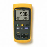
Components Figure 1. Components Table 3. Components xx Thermocouple T1 input Model 54: Thermocouple T2 input Holster 2 Display 1 Buttons Battery door Batteries aat01f.eps 53 & 54 Series II Getting Started 5 ...
Page 10
Series II Users Manual Display Elements Figure 2. Display Elements 6 xx The thermocouple measurement includes an offset. See "Changing Setup Options." The displayed readings do not change. ...
Page 11
Buttons Press to turn the thermometer on or off. Press , (CANCEL) to stop displaying the minimum, maximum, and average readings in the secondary display. (Shift function) Press , (CLEAR MEMORY) to delete logged readings from memory. Press , (PC/IR ...
Page 12
Series II Users Manual Press to freeze or unfreeze the displayed readings. Press when turning on the thermometer to test the display. All display elements appear. Model 54: Press the primary or secondary display. Press to start ...
Page 13
Using the Thermometer 1. Plug the thermocouple(s) into the input connector(s). 2. Press to turn on the thermometer. After 1 second the thermometer displays the first reading thermocouple is plugged into the selected input or the thermocouple is ...
Page 14
Series II Users Manual Changing the Logging Interval The logging interval determines how often the thermometer stores logged readings in memory. You choose the length of the logging interval. See "Using Memory." The thermometer stores logged readings ...
Page 15
Changing the Thermocouple Type 1. Press or until the display shows TYPE. 2. Press to display the thermocouple type choices. The currently selected thermocouple blinks. 3. Press or until the thermocouple you want appears on the display. 4. Press to ...
Page 16
Series II Users Manual Enabling or Disabling Sleep Mode The thermometer enters sleep mode if no button press occurs for 20 minutes. Pressing any button wakes the thermometer and returns it to its previous state. 1. Press ...
Page 17
Changing the Line Frequency For optimum rejection of line noise, set the thermometer for the local line frequency as follows: 1. Press or until the display shows 2. Press to indicate that you want to change the line setting. 3. ...
Page 18
Series II Users Manual Displaying Temperatures 1. Press to select the correct temperature scale. 2. Hold or attach the thermocouple(s) to the measurement location. The temperature reading appears in the selected display. 3. Model 54: Press to ...
Page 19
... At the end of the logging session you can view the logged readings on the display. You can also transfer the logged readings running FlukeView Forms software. (See "Communicating with a PC.") FlukeView Forms displays the logged readings on an online form, which you can print or store for later use. 53 & 54 Series II Using Memory 15 ...
Page 20
... The initial conditions are the thermocouple type and the offsets for each thermocouple input. You can only view initial conditions using FlukeView Forms . The data entries are a time stamp, the T1 reading, and the T2 and T1-T2 readings (Model 54) . You can view these values by pressing or using FlukeView Forms ...
Page 21
Clearing Memory When memory is full, appears on the display and logging stops. You can clear memory in normal or MIN MAX mode. Press , (CLEAR MEMORY) to delete logged readings from memory. The display shows the following for 2 ...
Page 22
... The display shows " -" if the log is empty. 18 Communicating with a PC You can transfer the contents of the thermometer’s memory using FlukeView Forms . The communication requires an IR (infrared) serial connection. Refer to the FlukeView Forms Installation Guide and FlukeView Help. FlukeView Forms places the logged readings into standard (default) or customized forms ...
Page 23
... To ensure that the thermometer performs to its accuracy specifications, Fluke recommends that you calibrate the thermometer annually, starting one year after purchase. To calibrate the thermometer, contact Fluke for the Service Center nearest you or follow the calibration procedure in the service manual listed in "Replacement Parts and Accessories." ...
Page 24
Series II Users Manual General Weight 280 g (10 oz) Dimensions 2.8 cm 7.8 cm 16.2 cm (without (1 6.4 in) holster) Battery 3 AA batteries P s Certification , Safety CSA C22.2 No. ...
Page 25
Electrical (cont.) Measurement J-, K-, T-, E-, and N-type: [0.05 o Accuracy, T1, T2 reading 0 T1-T2 (Model [below 100 C ( 148 54) of reading for J-, K-, E-, and N-type; and 0. ...
Page 26
Series II Users Manual 22 ...