MAL213836221E3 Vishay, MAL213836221E3 Datasheet - Page 8
MAL213836221E3
Manufacturer Part Number
MAL213836221E3
Description
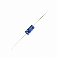
CAP 25V 220UF ELECT AXIAL
Manufacturer
Vishay
Series
AML138r
Type
Electrolyticr
Datasheet
1.MAL213838229E3.pdf
(12 pages)
Specifications of MAL213836221E3
Capacitance
220µF
Voltage Rating
25V
Tolerance
±20%
Lifetime @ Temp.
2000 Hrs @ 105°C
Operating Temperature
-40°C ~ 105°C
Features
General Purpose
Ripple Current
270mA
Esr (equivalent Series Resistance)
940.0 mOhm
Impedance
550 mOhm
Mounting Type
Through Hole
Package / Case
Axial, Can
Size / Dimension
0.394" Dia x 0.709" L (10.00mm x 18.00mm)
Tolerance (+ Or -)
20%
Voltage
25VDC
Esr
940mOhm
Mounting Style
Through Hole
Construction
Axial
Dcl
15uA
Lifetime
10000
Product Diameter (mm)
10mm
Product Height (mm)
Not Requiredmm
Product Depth (mm)
Not Requiredmm
Product Length (mm)
18mm
Seated Plane Height
Not Requiredmm
Lead Spacing (nom)
Not Requiredmm
Lead Diameter (nom)
0.8mm
Operating Temp Range
-40C to 105C
Operating Temperature Range
- 40 C to + 105 C
Termination Style
Axial
Dimensions
0.39 in Dia. x 0.71 in L
Product
High Temp Electrolytic Capacitors
Lead Free Status / RoHS Status
Lead free / RoHS Compliant
Height
-
Lead Spacing
-
Surface Mount Land Size
-
Lead Free Status / Rohs Status
Details
Other names
2222 138 36221
222213836221
4216PHTB
222213836221
4216PHTB


www.vishay.com
212
138 AML
Vishay BCcomponents
EQUIVALENT SERIES RESISTANCE (ESR)
IMPEDANCE (Z)
Table 4
Case Ø D x L = 10 x 30 to 21 x 38 mm
Z
Z
IMPEDANCE VS. CAPACITANCE VALUES (case Ø D x L = 6.3 mm x 12.7 mm to 10 mm x 25 mm)
10
10
10
0
1
+ 20 °C
- 25 °C
- 40 °C
-1
-2
- 60
T
amb
- 40
Fig.13 Typical multiplier of ESR as a function of
- 20
5500
2000
ambient temperature at 10 kHz
6.3 V
300
0
20
1200
3200
200
ESR
Case Ø D x L = 10 x 30 to 21 x 38 mm
ESR
10 V
ESR
40
For technical questions, contact:
0
0
2
1
0
= typical ESR at 20 °C, 100 Hz
10
60
Fig.12 Typical multiplier ESR as a function of frequency
2000
80
160
750
16 V
2
1
100
T
Axial Miniature, Long-Life
10
amb
Aluminum Capacitors
2
(°C)
120
Z x C
1500
120
560
25 V
R
( x µF) AT 10 kHz
aluminumcaps1@vishay.com
10
Case Ø D x L = 6.3 x 12.7 to 6.5 x 18 mm
( )
3
Ω
Z
10
10
10
10
1
3
2
-1
10
2
1200
450
40 V
Fig.14 Typical impedance as a function of frequency
90
10
Curve 1: 10 V
Curve 2: 100 V
4
1
2
f (Hz)
10
3
4
6
8
3
5
7
300
900
50 V
70
10
5
10
4
1
2
1500
Document Number: 28332
550
63 V
80
Curve 1: 10 µF, 63 V
Curve 2: 10 µF, 50 V
Curve 3: 22 µF, 63 V
Curve 4: 47 µF, 25 V
Curve 5: 100 µF, 16 V
Curve 6: 100 µF, 25 V
Curve 7: 220 µF, 10 V
Curve 8: 470 µF, 6.3 V
Revision: 16-Feb-11
10
5
1500
f (Hz)
100 V
550
T
80
amb
(°C)
10
6
Related parts for MAL213836221E3
Image
Part Number
Description
Manufacturer
Datasheet
Request
R

Part Number:
Description:
357-036-542-201 CARDEDGE 36POS DL .156 BLK LOPRO
Manufacturer:
Vishay
Datasheet:
Part Number:
Description:
357-036-542-201 CARDEDGE 36POS DL .156 BLK LOPRO
Manufacturer:
Vishay
Datasheet:
Part Number:
Description:
357-036-542-201 CARDEDGE 36POS DL .156 BLK LOPRO
Manufacturer:
Vishay
Datasheet:
Part Number:
Description:
357-036-542-201 CARDEDGE 36POS DL .156 BLK LOPRO
Manufacturer:
Vishay
Datasheet:
Part Number:
Description:
357-036-542-201 CARDEDGE 36POS DL .156 BLK LOPRO
Manufacturer:
Vishay
Datasheet:
Part Number:
Description:
357-036-542-201 CARDEDGE 36POS DL .156 BLK LOPRO
Manufacturer:
Vishay
Datasheet:
Part Number:
Description:
357-036-542-201 CARDEDGE 36POS DL .156 BLK LOPRO
Manufacturer:
Vishay
Datasheet:
Part Number:
Description:
357-036-542-201 CARDEDGE 36POS DL .156 BLK LOPRO
Manufacturer:
Vishay
Datasheet:
Part Number:
Description:
357-036-542-201 CARDEDGE 36POS DL .156 BLK LOPRO
Manufacturer:
Vishay
Datasheet:
Part Number:
Description:
357-036-542-201 CARDEDGE 36POS DL .156 BLK LOPRO
Manufacturer:
Vishay
Datasheet:
Part Number:
Description:
357-036-542-201 CARDEDGE 36POS DL .156 BLK LOPRO
Manufacturer:
Vishay
Datasheet:
Part Number:
Description:
357-036-542-201 CARDEDGE 36POS DL .156 BLK LOPRO
Manufacturer:
Vishay
Datasheet:
Part Number:
Description:
357-036-542-201 CARDEDGE 36POS DL .156 BLK LOPRO
Manufacturer:
Vishay
Datasheet:
Part Number:
Description:
357-036-542-201 CARDEDGE 36POS DL .156 BLK LOPRO
Manufacturer:
Vishay
Datasheet:
Part Number:
Description:
357-036-542-201 CARDEDGE 36POS DL .156 BLK LOPRO
Manufacturer:
Vishay
Datasheet: