GRM216R71H103KA01D Murata Electronics North America, GRM216R71H103KA01D Datasheet - Page 149
GRM216R71H103KA01D
Manufacturer Part Number
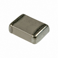
GRM216R71H103KA01D
Description
CAP CER 10000PF 50V 10% X7R 0805
Manufacturer
Murata Electronics North America
Series
GRMr
Datasheet
1.GNM1M2R61A105ME14D.pdf
(221 pages)
Specifications of GRM216R71H103KA01D
Capacitance
10000pF
Voltage - Rated
50V
Tolerance
±10%
Temperature Coefficient
X7R
Mounting Type
Surface Mount, MLCC
Operating Temperature
-55°C ~ 125°C
Applications
General Purpose
Package / Case
0805 (2012 Metric)
Size / Dimension
0.079" L x 0.049" W (2.00mm x 1.25mm)
Thickness
0.60mm
Lead Free Status / RoHS Status
Lead free / RoHS Compliant
Features
-
Ratings
-
Lead Spacing
-
Other names
490-1664-2
GRM40X7R103K050AD
GRM40X7R103K050AD
Available stocks
Company
Part Number
Manufacturer
Quantity
Price
Company:

Part Number:
GRM216R71H103KA01D
Manufacturer:
MURATA
Quantity:
804 000
Company:
Part Number:
GRM216R71H103KA01D
Manufacturer:
MURATA
Quantity:
8 680
Part Number:
GRM216R71H103KA01D 0805 X7R 103K 50V 17
Manufacturer:
MURATA/村田
Quantity:
20 000


!Note
• This PDF catalog is downloaded from the website of Murata Manufacturing co., ltd. Therefore, it’s specifications are subject to change or our products in it may be discontinued without advance notice. Please check with our
• This PDF catalog has only typical specifications because there is no space for detailed specifications. Therefore, please approve our product specifications or transact the approval sheet for product specifications before ordering.
sales representatives or product engineers before ordering.
!Note
Table 3 GNM, LLA Series for Reflow Soldering Land Dimensions
Table 4 LLM Series for Reflow Soldering Land Dimensions
2. Adhesive Application
1. Thin or insufficient adhesive can cause the chips to
2. Low viscosity adhesive can cause chips to slip after
3. Adhesive Coverage
Notice
GNMpp2
LLM
loosen or become disconnected during flow soldering.
The amount of adhesive must be more than dimension c,
shown in the drawing at right, to obtain the correct
bonding strength.
The chip's electrode thickness and land thickness must
also be taken into consideration.
mounting. The adhesive must have a viscosity of
5000Pa
Continued from the preceding page.
GRM18, GQM18
GRM21, LLL21, GQM21
GRM31, LLL31
• Please read rating and !CAUTION (for storage, operating, rating, soldering, mounting and handling) in this catalog to prevent smoking and/or burning, etc.
• This catalog has only typical specifications because there is no space for detailed specifications. Therefore, please approve our product specifications or transact the approval sheet for product specifications before ordering.
Part Number
Part Number
Part Number
•
GNM0M2
GNM1M2
s (500ps) min. (at 25 C).
GNM212
GNM214
GNM314
e
LLM21
LLM31
LLA18
LLA21
LLA31
a
Chip Capacitor
c
p
Chip Capacitor
p
d
f
0.6 to 0.8
Adhesive Coverage*
Land
1.0
c
1.37
a
0.9
2.0
2.0
3.2
1.6
2.0
3.2
L
0.05mg min.
0.15mg min.
0.1mg min.
b'
a
b
b
b=(c-e)/2, b'=(d-f)/2
c'
*Nominal Value
(0.3 to 0.5)
(0.3 to 0.5)
b, b'
1.25
1.25
1.25
0.6
1.0
1.6
0.8
1.6
W
c, c'
0.3
0.4
0.12 to 0.20*
0.4 to 0.5
0.6 to 0.7
0.6 to 0.7
0.8 to 1.0
0.3 to 0.4
0.5 to 0.7
0.7 to 0.9
GNMpp4
LLA
a
Dimensions (mm)
Dimensions (mm)
* 0.82Va+2bV1.00
2.0 to 2.6
3.2 to 3.6
Board
d
0.35 to 0.40*
0.35 to 0.45
0.25 to 0.35
0.35 to 0.6
0.5 to 0.7
0.5 to 0.7
0.7 to 0.9
0.4 to 0.7
b
c
1.3 to 1.8
1.6 to 2.0
Chip Capacitor
Chip Capacitor
e
Land
p
Adhesive
0.25 to 0.35
0.15 to 0.25
0.3 to 0.35
0.4 to 0.5
0.3 to 0.4
0.2 to 0.3
0.3 to 0.4
Continued on the following page.
0.3
1.4 to 1.6
c
Land
2.6
f
a=20 to 70 m
b=30 to 35 m
c=50 to 105 m
a
b
a
b
Notice
0.45
0.64
1.0
0.5
0.8
0.4
0.5
0.8
c
p
0.5
0.8
p
147
C02E.pdf
10.12.20
Related parts for GRM216R71H103KA01D
Image
Part Number
Description
Manufacturer
Datasheet
Request
R

Part Number:
Description:
BUZZER PIEZO 25VP-P SMD
Manufacturer:
Murata Electronics North America

Part Number:
Description:
CAP 4-ARRAY 680PF 100V X7R 1206
Manufacturer:
Murata Electronics North America
Datasheet:
Part Number:
Description:
CAP 4-ARRAY 1000PF 100V X7R 1206
Manufacturer:
Murata Electronics North America
Datasheet:
Part Number:
Description:
CAP 4-ARRAY 1800PF 100V X7R 1206
Manufacturer:
Murata Electronics North America
Datasheet:
Part Number:
Description:
CAP 4-ARRAY 68000PF 16V X7R 1206
Manufacturer:
Murata Electronics North America
Datasheet:

Part Number:
Description:
CAP CER 1000PF 50V 10% X7R 0402
Manufacturer:
Murata Electronics North America
Datasheet:
Part Number:
Description:
CAP CER 10000PF 16V 10% X7R 0402
Manufacturer:
Murata Electronics North America
Datasheet:

Part Number:
Description:
CAP 5.5-25PF 2.5X3.2MM SMD
Manufacturer:
Murata Electronics North America
Datasheet:

Part Number:
Description:
CAP 4.5-20PF 2.5X3.2MM SMD
Manufacturer:
Murata Electronics North America
Datasheet:

Part Number:
Description:
CAP 5.0-20PF 3.2X4.5MM SMD RED
Manufacturer:
Murata Electronics North America
Datasheet:

Part Number:
Description:
CAP 2.0-6.0PF 3.2X4.5MM SMD BLU
Manufacturer:
Murata Electronics North America
Datasheet:

Part Number:
Description:
CAP 1.4-3.0PF 3.2X4.5MM SMD BRN
Manufacturer:
Murata Electronics North America
Datasheet:

Part Number:
Description:
CAP 3.0-10PF 3.2X4.5MM SMD WHT
Manufacturer:
Murata Electronics North America
Datasheet:

Part Number:
Description:
CAP 2.0-6.0PF 4X4.5MM TOPADJ BLU
Manufacturer:
Murata Electronics North America
Datasheet:

Part Number:
Description:
CAP 8.5-40PF 4X4.5MM TOPADJ YEL
Manufacturer:
Murata Electronics North America
Datasheet: