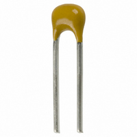
C315C332K1R5TA Kemet, C315C332K1R5TA Datasheet - Page 3

C315C332K1R5TA
Manufacturer Part Number
C315C332K1R5TA
Description
CAP 3300PF 100V 10% CER RADIAL
Manufacturer
Kemet
Series
Golden Max™r
Specifications of C315C332K1R5TA
Capacitance
3300pF
Voltage - Rated
100V
Tolerance
±10%
Temperature Coefficient
X7R
Mounting Type
Through Hole
Operating Temperature
-55°C ~ 125°C
Applications
General Purpose
Package / Case
Radial
Size / Dimension
0.210" L x 0.150" W (5.33mm x 3.81mm)
Thickness
2.54mm Max
Lead Spacing
0.100" (2.54mm)
Lead Style
Straight
Dielectric Characteristic
X7R
Capacitance Tolerance
± 10%
Voltage Rating
100VDC
Capacitor Case Style
Radial Leaded
No. Of Pins
2
Rohs Compliant
Yes
Termination Style
Radial
Operating Temperature Range
- 55 C to + 125 C
Product
Conformally Coated MLCCs
Dimensions
2.54 mm W x 3.81 mm L x 5.33 mm H
Dissipation Factor Df
2.5
Material, Element
Ceramic
Termination
Radial
Voltage, Rating
100 VDC
Lead Free Status / RoHS Status
Lead free / RoHS Compliant
Features
-
Ratings
-
Lead Free Status / Rohs Status
Lead free / RoHS Compliant
Other names
399-4176
CERAMIC
CASE SIZE
(See Table Above)
SPECIFICATION
C — Standard
CAPACITANCE, CODE
Expressed in Picofarads (pF)
First Two Digits — Significant Figures
Third Digit — Number of Zeros (Use 9 for 1.0
thru 9.9 pF. Example: 2.2pF — 229)
CAPACITANCE TOLERANCE
D — 0.5 pF
F — 1%
G — 2%
J — 5%
*Part Number Example: C320C102M1R5CA (14 digits – no spaces)
CASE
SIZE
C315
C317
C320
C322
C323
C330
C333
C340
C350
Drawings are not to scale. See table below for dimensions.
See page 10 for optional lead configurations.
1 inch = 25.4 mm.
(1) Measured at seating plane.
Case
C315
C317
C320
C322
C323
C330
C333
C340
C350
Size
*.276 (7.00) MIN.
C317
C322
C330
© KEMET Electronics Corporation, P.O. Box 5928, Greenville, S.C. 29606, (864) 963-6300
S
0.400 (10.16)
0.500 (12.70)
0.150 (3.81)
0.150 (3.81)
0.200 (5.08)
0.200 (5.08)
0.200 (5.08)
0.300 (7.62)
0.300 (7.62)
.400 (10.16)
.500 (12.70)
CERAMIC CONFORMALLY COATED/RADIAL
.150 (3.81)
.150 (3.81)
.200 (5.08)
.200 (5.08)
.200 (5.08)
.300 (7.62)
.300 (7.62)
K — 10%
M — 20%
P — 0%, +100%
Z — -20, +80%
STANDARD LEAD CONFIGURATION — OUTLINE DRAWINGS
Max.
MAX.
L
L
H
*
“STANDARD & HIGH VOLTAGE GOLDEN MAX”
For packaging information, see pages 40, and 41.
DIMENSIONS — INCHES & MILLIMETERS
0.460 (11.68)
0.560 (14.22)
C
0.210 (5.33)
0.230 (5.84)
0.260 (6.60)
0.260 (6.60)
0.320 (8.13)
0.360 (9.14)
0.390 (9.91)
320
C323
Max
.460 (11.68)
.560 (14.22)
H.
S
ORDERING INFORMATION
.210 (5.33)
.230 (5.84)
.260 (6.60)
.260 (6.60)
.320 (8.13)
.360 (9.14)
.390 (9.91)
MAX.
H
C
102
H
*
Standard
0.100
0.100
0.125
0.125
0.125
0.150
0.150
0.150
0.200
Max.
T
M
1
.130 (3.30)
.130 (3.30)
.150 (3.81)
.150 (3.81)
.150 (3.81)
.200 (5.08)
.200 (5.08)
.200 (5.08)
.250 (6.35)
C333
MAX.
S
R
T
Voltage
T Max.
0.150
0.150
0.200
0.200
0.200
0.250
0.250
0.270
0.270
High
5
T
H
*
A
0.400 (10.16)
*
0.100 (2.54)
0.200 (5.08)
0.100 (2.54)
0.200 (5.08)
0.200 (5.08)
0.200 (5.08)
0.200 (5.08)
0.200 (5.08)
(1.52)
MAX.
±.030 (.78)
.060
±.030 (.78)
FAILURE RATE
A — Not Applicable
D
S(1)
TERMINATION MATERIAL
T — 100% Tin
H — SnPb
C — 100% Sn
INTERNAL
CONSTRUCTION
5 — Standard
DIELECTRIC
EIA Designation
G — C0G (NP0) — Ultra-Stable
R — X7R — Stable
U — Z5U — General Purpose
RATED VOLTAGE
2 — 200
1 — 100
5 — 50
C — 500
D — 1000
.400 (10.16)
S(1)
.100 (2.54)
.200 (5.08)
.100 (2.54)
.200 (5.08)
.200 (5.08)
.200 (5.08)
.200 (5.08)
.200 (5.08)
(Not recommended for new design)
C315
C320
C330
C340
C350
L
S
F — 1500
G — 2000
Z — 2500
H — 3000
-.001(.025)
0.020 (.51)
0.020 (.51)
0.020 (.51)
0.020 (.51)
0.020 (.51)
0.020 (.51)
0.020 (.51)
0.020 (.51)
0.025 (.64)
+.004(.10)
+.004 (.10)- .001 (.025)
D
H
*
.020 (.51)
.020 (.51)
.020 (.51)
.020 (.51)
.020 (.51)
.020 (.51)
.020 (.51)
.020 (.51)
.025 (.64)
D
T
9


