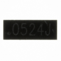
RCLAMP0524J.TCT Semtech, RCLAMP0524J.TCT Datasheet - Page 6

RCLAMP0524J.TCT
Manufacturer Part Number
RCLAMP0524J.TCT
Description
TVS ARRAY SLP2710P8 8-PIN
Manufacturer
Semtech
Series
RailClamp®r
Datasheet
1.RCLAMP0524J.TCT.pdf
(11 pages)
Specifications of RCLAMP0524J.TCT
Mfg Application Notes
TVS Diode AppNote SI07-12
Voltage - Reverse Standoff (typ)
5V
Voltage - Breakdown
6V
Power (watts)
150W
Polarization
4 Channel Array - Bidirectional
Mounting Type
Surface Mount
Package / Case
SLP2710P8
Lead Free Status / RoHS Status
Lead free / RoHS Compliant
Other names
RCLAMP0524JTR
Available stocks
Company
Part Number
Manufacturer
Quantity
Price
Company:
Part Number:
RCLAMP0524J.TCT
Manufacturer:
SEMTECH
Quantity:
840
Part Number:
RCLAMP0524J.TCT
Manufacturer:
SEMTECH/美国升特
Quantity:
20 000
requirement of 100 Ohm ±15% with plenty of margin.
For signal integrity purposes, the best results will be
obtained by using the RClamp0524J to protect the
high-speed differential pairs. This is because the
device is designed such that the data lines from the
connector line up with the I/O pins of the device
without altering the trace routing. Either the
RClamp0504P or RClamp0524J may be used to
protect the remaining lines (I
depending on layout constraints.
Layout Guidelines for Optimum ESD Protection
Good circuit board layout is critical not only for signal
integrity, but also for effective suppression of ESD in-
duced transients. For optimum ESD protection, the
following guidelines are recommended:
PROTECTION PRODUCTS
© 2008 Semtech Corp.
Applications Information
Place the device as close to the connector as pos-
sible. This practice restricts ESD coupling into
adjacent traces and reduces parasitic inductance.
The ESD transient return path to ground should be
kept as short as possible. Whenever possible, use
multiple micro vias connected directly from the device
ground pad to the ground plane.
Avoid running critical signals near board edges.
2
C, CEC, and hot plug)
6
Note: Measurements were taken on SLP HDMI EVAL Rev C Board that has 100Ω
differential traces impedance throughout (No trace Compensation).
Figure 2 - TDR Measurement with 200ps risetime
Figure 3 - TDR Measurement with 100ps risetime
X-axis
Y-axis
X-axis
Y-axis
using Semtech Evaluation Board
using Semtech Evaluation Board
1.905
101.0
1.80
A
96
A
2.081
107.0
A
A
B
B
A
A
RClamp0524J
B
B
2.076
108.0
B
B
PRELIMINARY
(nsec)
(Ohm)
(nsec)
(Ohm)
www.semtech.com


