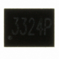
UCLAMP3324P.TCT Semtech, UCLAMP3324P.TCT Datasheet - Page 4

UCLAMP3324P.TCT
Manufacturer Part Number
UCLAMP3324P.TCT
Description
TVS ARRAY UCLAMP 3.3V 8-SLP
Manufacturer
Semtech
Series
µClamp™r
Datasheet
1.UCLAMP3324P.TCT.pdf
(6 pages)
Specifications of UCLAMP3324P.TCT
Voltage - Reverse Standoff (typ)
3.3V
Power (watts)
40W
Polarization
4 Channel Array - Unidirectional
Mounting Type
Surface Mount
Package / Case
8-SLP
Lead Free Status / RoHS Status
Lead free / RoHS Compliant
Voltage - Breakdown
-
Other names
UCLAMP3324PTR
Available stocks
Company
Part Number
Manufacturer
Quantity
Price
Company:
Part Number:
UCLAMP3324P.TCT
Manufacturer:
Semtech
Quantity:
6 000
Company:
Part Number:
UCLAMP3324P.TCT
Manufacturer:
SEMTECH
Quantity:
215 600
Device Connection Options
The µClamp3324P is designed to protect four lines. It
will present a high impedance to the protected line up
to 3.3 volts. It will “turn on” when the line voltage
exceeds 3.5 volts. The device is unidirectional and
may be used on lines where the signal polarity is above
ground.
Flow Thru Layout
The µClamp3324P is designed for ease of PCB layout
by allowing the traces to enter one side of the device
and exit the other side. Figure 2 shows the
recommended way to design the PCB board traces in
order to use the flow through layout. The solid line
represents the PCB trace. Note that the PCB traces
enter at the input pin and exit from the opposite pin.
(pin 1 to pin 8, pin 2 to pin 9, pin 3 to pin 6, pin 4 to
pin 5). For example, line 1 enters at pin 1 and exits at
Pin 8. The bottom tab is connected to ground. This
connection should be made directly to a ground plane
on the board for best results. The path length is kept
as short as possible to minimize parasitic inductance.
EPD TVS Characteristics
These devices are constructed using Semtech’s
proprietary EPD technology. The structure of the EPD
TVS is vastly different from the traditional pn-junction
devices. At voltages below 5V, high leakage current
and junction capacitance render conventional ava-
lanche technology impractical for most applications.
However, by utilizing the EPD technology, these devices
can effectively operate at 3.3V while maintaining
excellent electrical characteristics.
The EPD TVS employs a complex nppn structure in
contrast to the pn structure normally found in tradi-
tional silicon-avalanche TVS diodes. The EPD mecha-
nism is achieved by engineering the center region of
the device such that the reverse biased junction does
not avalanche, but will “punch-through” to a conduct-
ing state. This structure results in a device with supe-
rior DC electrical parameters at low voltages while
maintaining the capability to absorb high transient
currents.
PROTECTION PRODUCTS
Applications Information
2005 Semtech Corp.
4
Figure 3 - EPD TVS IV Characteristic Curve
In 1
In 2
In 3
In 4
1
Figure 2 - Layout Example
Figure 1 - Circuit Diagram
8
2
V
F
7
GND
I
I
I
I
SB
PT
PP
R
uClamp3324P
I
F
3
6
V
RWM
www.semtech.com
V
4
SB
Out 1
Out 2
Out 3
Out 4
V
PT
V
C
5


