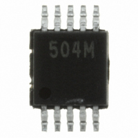
RCLAMP0504M.TBT Semtech, RCLAMP0504M.TBT Datasheet - Page 8

RCLAMP0504M.TBT
Manufacturer Part Number
RCLAMP0504M.TBT
Description
IC TVS ARRAY 4-LINE 5V 10MSOP
Manufacturer
Semtech
Series
RailClamp®r
Datasheet
1.RCLAMP0504M.TBT.pdf
(10 pages)
Specifications of RCLAMP0504M.TBT
Voltage - Reverse Standoff (typ)
5V
Voltage - Breakdown
6V
Power (watts)
300W
Polarization
4 Channel Array - Bidirectional
Mounting Type
Surface Mount
Package / Case
10-MSOP, Micro10™, 10-uMAX, 10-uSOP
Lead Free Status / RoHS Status
Lead free / RoHS Compliant
Other names
RCLAMP0504MTR
Available stocks
Company
Part Number
Manufacturer
Quantity
Price
Company:
Part Number:
RCLAMP0504M.TBT
Manufacturer:
SEM
Quantity:
20 000
Company:
Part Number:
RCLAMP0504M.TBT
Manufacturer:
SEMTECH
Quantity:
2 003
Part Number:
RCLAMP0504M.TBT
Manufacturer:
SEMTECH/美国升特
Quantity:
20 000
Company:
Part Number:
RCLAMP0504M.TBT(504M)
Manufacturer:
IR
Quantity:
12 000
DVI Protection
The small geometry of a typical digital-visual interface
(DVI) graphic chip will make it more susceptible to
electrostatic discharges (ESD) and cable discharge
events (CDE). Transient protection of a DVI port can be
challenging. Digital-visual interfaces can often transmit
and receive at a rate equal to or above 1Gbps. The
high-speed data transmission requires the protection
device to have low capacitance to maintain signal
integrity and low clamping voltage to reduce stress on
the protected IC. The
insertion loss of <0.4dB at 1GHz (I/O to ground) to
ensure signal integrity and can protect the DVI interface
to the 8kV contact and 15kV air ESD per IEC 61000-4-
2 and CDE.
PROTECTION PRODUCTS
Applications Information (continued)
2004 Semtech Corp.
RClamp0504M
Figure 7 - Digital Video Interface (DVI) Protection
1
1
has a low typical
8
Figure 7 shows how to design the
DVI circuit on a flat panel display and a PC graphic card.
The
mode and differential mode protection. The internal TVS
of the
power pin of the DVI circuit does not come out through
the connector and is not subjected to external ESD
pulse; therefore, pin 3 should be left unconnected.
Connecting pin 3 to Vcc of the DVI circuit may result in
damage to the chip from ESD current.
RClamp0504M
RClamp0504M
1
1
is configured to provide common
acts as a 5 volt reference. The
RClamp0504M
RClamp0504M
PRELIMINARY
www.semtech.com
into the


