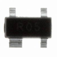
SR05.TCT Semtech, SR05.TCT Datasheet - Page 6

SR05.TCT
Manufacturer Part Number
SR05.TCT
Description
IC TVS ARRAY 2-LINE 5V SOT-143
Manufacturer
Semtech
Series
RailClamp®r
Datasheet
1.SR05.TCT.pdf
(9 pages)
Specifications of SR05.TCT
Voltage - Reverse Standoff (typ)
5V
Voltage - Breakdown
6V
Power (watts)
500W
Polarization
2 Channel Array - Unidirectional
Mounting Type
Surface Mount
Package / Case
SOT-143, SOT-143B, TO-253AA
Lead Free Status / RoHS Status
Lead free / RoHS Compliant
Other names
SR05TR
Available stocks
Company
Part Number
Manufacturer
Quantity
Price
Company:
Part Number:
SR05.TCT
Manufacturer:
NXP
Quantity:
10 802
Part Number:
SR05.TCT
Manufacturer:
SEMTECH/美国升特
Quantity:
20 000
SR05
PROTECTION PRODUCTS
Applications Information (continued)
the power supply connection. During an ESD event,
the current will be directed through the integrated TVS
diode to ground. The total clamping voltage seen by
the protected IC due to this path will be:
V
= V
+ V
C
F(RailClamp)
TVS
This is given in the data sheet as the rated clamping
voltage of the device. For a SR05 the typical clamping
voltage is <16V at I
=30A. The diodes internal to the
PP
RailClamp are low capacitance, fast switching devices
that are rated to handle transient currents and main-
tain excellent forward voltage characteristics.
Universal Serial Bus ESD Protection
The figure below illustrates how to use the SR05 to
protect one upstream USB port and the SRDA05-4 to
protect two downstream USB ports. When the voltage
on the data lines exceed the bus voltage (plus one
diode drop), the internal rectifiers are forward biased
conducting the transient current away from the pro-
tected controller chip. The TVS diode directs the surge
to ground. The TVS diode also acts to suppress ESD
strikes directly on the voltage bus. Thus, both power
and data pins are protected with a single device.
Reference Semtech application note SI96-18 for
further information.
Matte Tin Lead Finish
Matte tin has become the industry standard lead-free
replacement for SnPb lead finishes. A matte tin finish
is composed of 100% tin solder with large grains.
Since the solder volume on the leads is small com-
pared to the solder paste volume that is placed on the
land pattern of the PCB, the reflow profile will be
determined by the requirements of the solder paste.
Therefore, these devices are compatible with both
lead-free and SnPb assembly techniques. In addition,
unlike other lead-free compositions, matte tin does not
have any added alloys that can cause degradation of
the solder joint.
www.semtech.com
2005 Semtech Corp.
6


